Skip to main content  ∨   Page logos with links to institutions:
Max Planck Society Max Planck Institute for Nuclear Physics University of Heidelberg
Stored and Cooled Ions Division
 
Max Planck SocietyMax Planck Institute for Nuclear PhysicsUniversity of Heidelberg Stored and Cooled Ions Division
Superordinated navigation: MPIK Homepage  |  Home  |  Deutsch  |  Sitemap  |  Search  |  Contact
Section navigation:
LIONTRAP

Contact  Contact


Tel.: +49 6221 516-851
Fax: +49 6221 516-852
Postal Address
Max Planck Institute for Nuclear Physics
P.O. Box 10 39 80
69029 Heidelberg
Visitor Address
Max Planck Institute for Nuclear Physics
Saupfercheckweg 1
Building: Gentner lab, room 134
69117 Heidelberg


Experimental setup

Experimental Setup
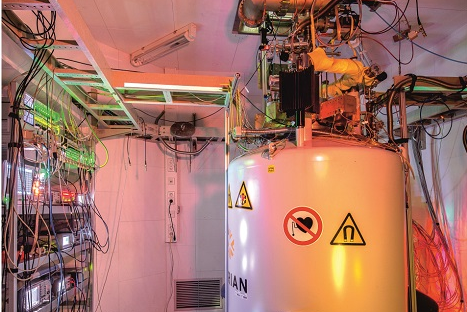
Figure 1: Experimental Setup

In order to be able to carry out this high-precision measurement for several weeks with as little disturbance as possible, a vacuum of 10-16 mbar or better is required. The trap tower, consisting of the two storage traps and the precision trap along with the ion source, is located in a hermetically sealed vacuum chamber which is cooled to about 4.2 K with liquid helium. To achieve this extreme vacuum, the vacuum chamber is pumped to a UHV vacuum at room-temperature and then hermetically sealed using a cold-welding ("pinch off") technique. When this vessel is then cooled to 4 K, the remaining gas freezes out on the surfaces, resulting in a pressure 10-16 mbar. The sealed chamber brings in the necessity of internal ion sources as external access is no more possible. At the top of the trap chamber there are numerous vacuum feedthroughs for the electron beam acceleration voltage, trap voltages, the detection and excitation lines. Between the trap chamber and the liquid helium reservoir is a cryogenic electronics section, which contains resonators, amplifiers, filters and switches for the excitation lines. The trap chamber, the cryogenic electronics section, the liquid helium reservoir, hang vertically in the 13 cm wide, vertical, warm bore of the 3.76 T superconducting magnet. See Figure 1.


^ to the top

In situ ion production

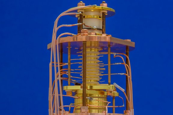
Miniature Electron Beam Ions Source section of the trap tower.
Figure 2: Miniature Electron Beam Ions Source section of the trap tower.

Ions are produced using a miniature electron beam ion source (mEBIS) [1, 2], see Figure 2. The electrons are extracted from a field emission point (FEP) by applying a voltage difference of at least 700 V between the FEP and the acceleration electrode. These electrons then pass through a 700 μm hole in the target. Biasing the reflector electrode to a voltage lower than the FEP, the emitted electrons start oscillating along the magnetic field lines between the FEP and the reflector forming a stationary electron beam. The electron beam widens and impinges on the target. This ablates atoms, which diffuse into the electron beam and get ionized. These low charged ions are confined in the creation trap (CT), a simple cylindrical Penning trap, comprising three electrodes, a ring and two endcap electrodes. Further electron-impact ionization produces ions in higher charge states, in particular lots of carbon, oxygen and silicon ions. The maximal accessible charge states are limited by the voltage difference between the FEP and the ring electrode of the CT.

Since only a limited number of ions are required for the experiment, the extra ions are removed. Different techniques can be used to remove the extra ions. One of these techniques (called the magnetron cleaning) would be to use broadband white noise, which increases the radius of gyration of all ions until they eventually hit the electrode surface. Simultaneously, selective cooling of the magnetron motion of the ion of interest is done by (resonant) sideband coupling with the axial motion (which in turn is cooled by the tank circuit) at the q/m sensitive frequency νk = ν-z. Consequently, the magnetron motion of all other ions increases until they hit the surfaces of the electrodes and get lost.

An additional method for single species ion production is applied by using broadband axial excitation with a frequency range above the magnetron frequency and below 2νz, but leaving out selectively the axial frequency of the ion of interest, which increases the axial temperature of all other ions. After this excitation the trap potential is dipped towards Ur ≈ -100 mV for one second. The axially hot ions are removed by this procedure, while the ion of interest, which has been resonantly cooled via the tank circuit, stays trapped. Observing the disappearance of single peaks of individual ions in the frequency spectrum of the resonator proves that the extra ions are lost. The trap potential is then reset to the original value and remaining ions are cooled and the process is repeated to have a single ion at last. The isolated single ion is then transported to ST-I and above process is repeated to generate another ion in the PT.

Ion source(target) in use at present:

Recently we have also succeeded for the first time in producing single deuterium ions with our ion source (mEBIS). For this purpose, a layer of deuterated molecules is printed on to a carbon nanotube filled and thus conductive, PEEK target. To allow efficient production of deuteron atomic and molecular ions a drop-on-demand printing system is used [3].

Ion source for Helium mass measurement:

Helium-3 atoms, being inert, have very weak bonding capabilities and thus the technique using the PEEK target cannot be used for helium-3 ion production. Hence, a new form of production scheme is under development and study, where helium-3 atoms (gas) are carefully released on demand and guided to the electron beam for impact ionisation as discussed above. This involves using an adsorption agent for the helium-3 gas, which is highly porous active charcoal at 4K, and then heating the system to evaporate the helium-3 atoms when necessary. Limiting the amount of helium-3 released into the trap chamber is mandatory in order to maintain the vacuum and to prevent contamination of the trap electrodes.

^ to the top

Doubly compensated Penning trap for high precision measurements

Light atomic ions, due to their low charge, lead to very small signals which makes their study challenging. The development of a special trap design with extremely good harmonicity enables the adjustment of the electrostatic potential in a way that contributions to the systematic error budget can be made completely negligible. This allows one to amplify the ions' motion to large amplitudes for achieving a sufficient signal to apply PnA. The LIONTRAP experiment has been specifically optimized for this purpose.

The electrostatic potential along the trap axis Φ(z) of a cylindrical trap can be expressed as an expansion, Eq. (4), where Ur is the applied ring voltage and dchar=√(2dz02+r02)/4 is characteristic trap size, defined by the trap radius r0 and the axial distance of the endcap from the trap centre dz0.

Φ(z) = Ur/2 (C0 + C2·z2/dchar2 + C4·z4/dchar4 + C6·z6/dchar6 + …)(4)

To achieve an ideal trapping potential, all coefficients Cn with n ≥ 4 should be nulled: C4 = C6 = … = C = 0.

Cylindrical Penning trap design.
Figure 3: Cylindrical Penning trap design. Vertical cut through the seven-electrode design of the precision trap, including all adjustment parameters. When cooling the assembled trap to 4.2 K, the electrodes shrink onto the sapphire rings (blue) due to a larger thermal expansion coefficient, resulting in a self-alignment of the electrodes. The split electrodes are arranged on T-shaped quartz glass rings. The copper rings (brown) are used for the fixation of the three split inner electrodes.

Conventional high-precision Penning traps have five cylindrical electrodes. They consist of one ring electrode, one pair of correction electrodes and one pair of end cap electrodes to shape a harmonic potential and cancel leading order anharmonicities in the electric potential. With a suitable ratio of the ring and correction electrode lengths, the voltage at the correction electrodes can be used to set the higher electrical potential coefficients C4 and C6 to zero. Such a trap is called compensated. The pair of end-cap electrodes which enclose the correction electrode are normally grounded.

The LIONTRAP PT is a more sophisticated seven-electrode cylindrical Penning trap where a second pair of correction electrodes is added, see Figure 3. The two end cap electrodes are segmented to provide adiabatic transport of the ions. It is one of the first doubly compensated traps.

In a five-electrode cylindrical Penning trap the coefficient C2 is:

C2 = D2 (Uc/Ur) + E2,(5)

where Uc is the voltage applied to the correction electrodes and the ratio Uc/Ur is known as the tuning ratio. The axial frequency νz ∝ √C2, therefore it convenient to make C2 independent of the correction voltage and thus D2=0. Such a trap where the axial frequency is independent of the correction voltage Uc is said to be orthogonal.

For two pairs of correction electrodes D2,1=D2,2=0 ("double orthogonality") would be desired:

C2 = D2,1 (Uc1/Ur) + D2,2 (Uc2/Ur) + E2(6)

However, this double orthogonality cannot be achieved, provided that the radius is fixed and constant for all electrodes. Therefore, we go for a combined orthogonality in LIONTRAP as:

D2comb ≡ D2,1 (Uc1/Ur) + D2,2 (Uc2/Ur) = 0(7)

In a seven-electrode cylindrical Penning trap there are 5 degrees of freedom – the compensation voltage Uc, the length of the ring, the length of the first correction electrodes, the length of the second correction electrode and their applied voltages. Thus, design of a doubly compensated trap is wrapped around these features C4=C6=C8=C10=D2comb=0. The precision trap of the LIONTRAP experiment is designed to have C2=−0.5997 and dchar=5.107 mm.

The anharmonicities created due to geometric uncertainties can be corrected by applying proper potentials to the correction electrode and thus the harmonicity can be optimized in-situ. Systematic studies of this optimization are performed to achieve the required highly harmonic electrical trapping potential.


^ to the top

Detection system

In the apparatus for the proton measurement, we used one tank circuit for axial frequency detection in the Magnetometer trap (MT) and four tank circuits are connected to separate electrodes of the precision trap (PT) for the detection of the axial and cyclotron motion of the ions of interest, see Figure 4. All applied voltages are kept the same for both species in order to null parasitic position shifts due to machining and surface imperfections. However, this requires to have the respective resonator exactly at the correct ratio of frequencies. To this end, the carbon axial resonator in the PT is equipped with a voltage-variable capacitor that allows fine-tuning of its resonance frequency to the ion's axial frequency [4] in-situ at cryogenic temperature. The same applies to the cyclotron resonators used to detect the modified cyclotron frequencies of the two ions, since the magnetic field of the superconducting magnet cannot easily be tuned to fit the ions' modified cyclotron frequencies to the resonator's resonance frequency.

Sketch of the complete trap tower.
Figure 4: Sketch of the complete trap tower including all detection systems and excitation lines of the LIONTRAP experiment during the proton mass measurement campaign. Besides the precision trap (PT) four other traps are shown: two storage traps (ST-I, ST-II), the magnetometer trap (MT), and the creation trap (CT). Additionally, there are several transport electrodes. The green tank circuit is the axial detection system for the magnetometer trap, whereas the two blue circuits are designed for the proton and the red ones are for the carbon ion. The black connections symbolize the four excitation lines. The cone, at the upper side of ST-I, is part of a cleaning technique to remove unwanted ions, which can be utilized in the future.

The PT is equipped with different excitation lines. The quadrupole excitation Qxz is connected to one half of the lower correction electrode and is used for sideband RF cooling and to drive the double dips of the ions. Additionally, it is used for the PnA method to transfer the modified cyclotron phase to the axial phase. The dipole excitation Dx is connected to one half of the ring electrode and is used to provide radial excitation for the isolation of ions. The axial dipole excitation Dz is connected to the outer correction electrode to do axial sweep excitations mainly during the preparation of single ions. These excitation lines are connected using cryogenic attenuators and transistor switches to suppress residual rf-noise coupling to the trap electrodes [5]. Another Qxz quadrupole drive is connected to the MT to enable the PnA method in this trap.

^ to the top

References

[1]   B. Schabinger et al., "Towards a g-factor determination of the electron bound in highly-charged calcium ions" externer Link, Journal of Physics: Conference Series, vol. 58, pp. 121-124, 2007.
[2]   S. Sturm, K. Blaum, B. Schabinger, A. Wagner, W. Quint, and G. Werth, "On g-factor experiments with individual ions" externer Link, Journal of Physics B: Atomic, Molecular and Optical Physics, vol. 43, no. 7, 2010.
[3]   R. Haas, S. Lohse, C. E. Düllmann, K. Eberhardt, C. Mokry, and J. Runke, "Development and characterization of a Drop-on-Demand inkjet printing system for nuclear target fabrication" externer Link, Nuclear Instruments and Methods in Physics Research Section A: Accelerators, Spectrometers, Detectors and Associated Equipment, vol. 874, pp. 43-49, 2017.
[4]   H. Nagahama et al., "Highly sensitive superconducting circuits at approximately 700 kHz with tunable quality factors for image-current detection of single trapped antiprotons" externer Link, Rev. Sci. Instrum., vol. 87, no. 11, p. 113305, Nov 2016.
[5]   S. Sturm, "The g-factor of the electron bound in 28Si13+: The most stringent test of bound-state quantum electrodynamics" externer Link, Ph.D., Johannes Gutenberg University Mainz, 2012.