Measurement principle
Penning trap basics
For high-precision measurements on single ions (e.g. mass, g-factor measurements), the charged particles are nowadays stored and analysed using Penning traps. The confinement of a particle in a Penning trap is attained by the use of a strong, homogeneous magnetic field that keeps the ions radially confined and an electric quadrupole potential that stores them axially (along the magnetic field lines).
In its simplest form the electric quadrupole potential is achieved by three cylindrically symmetric electrodes stacked in the axial direction. The upper and lower electrodes (endcaps) are at ground potential and the voltage of the inner electrode (ring electrode) is negative for positively charged particles. This is discussed in detail in the section doubly compensated Penning trap for high precision measurements.
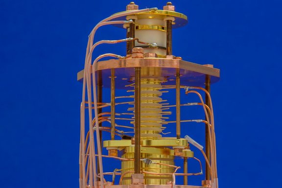
To generate the static quadrupole potential, typically either cylindrical or hyperbolical electrode geometries are used. At LIONTRAP we use only cylindrically shaped electrodes firstly, because they can be manufactured with a very high precision of about 10 μm, secondly because the individual ions can be transported easily along the axis of cylindrical symmetry, that is along the magnetic field lines, between different Penning traps, and thirdly, cylindrical electrodes can be further subdivided into additional compensation electrodes relatively easily.
The combination of the two static fields yields a motion of the stored ion which can be divided into three harmonic eigenmotions, see Figure 1. In the axial direction, the ion oscillates with an axial frequency νz dependent solely on the electrostatic trapping potential. In the horizontal direction, the original undisturbed cyclotron oscillation splits into two circular motions due to the additional electric quadrupole potential: The modified cyclotron motion (also called reduced cyclotron motion) with the modified cyclotron frequency ν+ and the very slow magnetron movement with the magnetron frequency ν-. The actual cyclotron frequency can be calculated from the following invariance theorem [1]:
νc2 = ν+2 + νz2 + ν-2(1)
This equation is independent of a possible tilt between the magnetic field and the electrostatic quadrupole potential as well as an elliptic deformation of the electrostatic quadrupole potential.
Cyclotron frequency ratio
High-precision mass determinations on stable atomic nuclei or ions are based on very precise cyclotron frequency measurements, which are performed on individually stored ions. The cyclotron frequency νc of the ion depends on the charge of the ion q, its mass m and the strength of the homogeneous magnetic field B0:
νc = 1/2π · q/m · B0(2)
To accurately determine B0, a reference ion is used where the mass mref is known with a higher relative accuracy than for the ion of interest. The cyclotron frequencies of the ion of interest and the reference ion must be determined in the same magnetic field. Ideally, a carbon ion is used as the reference mass, since the atomic mass unit is defined by the usual carbon atom 12C and therefore has no uncertainty. The mass of a carbon nucleus must be corrected for the masses and binding energies of the six missing electrons in comparison to the carbon atom. However, the relative uncertainty of this correction is smaller than 8·10-14 and therefore does not currently limit any mass measurement. The following therefore applies to the mass to be determined
m = q/qref · νcref/νc · mref(3)
The charge ratio (q/qref) is a known integer ratio. The essential parameter for mass determinations is therefore the high-precision measurement of a cyclotron frequency ratio (CFR, νcref/νc). Ideally, the ratio of cyclotron frequencies has to be measured simultaneously at the same position in order to nullify the magnetic field fluctuation. The group at MIT working with David Pritchard has so far come closest to this ideal measuring principle by storing both ions together in one trap (on a common magnetron radius, see below) and then measuring the two cyclotron frequencies simultaneously [2]. However, this measurement principle places very strong constraints on the reference ion, which must have a mass almost identical to that of the ion to be determined. In other words, both ions must form an almost perfect mass doublet.
At LIONTRAP we approach this ideal measuring principle in a completely different way. First, we prepare an individually stored light atomic nucleus, whose mass is to be determined, and an individually stored carbon ion in adjacent Penning traps. To determine the two cyclotron frequencies, we transport both ions alternately into our Precision Trap (PT). To measure the two cyclotron frequencies under identical conditions, the same trap configuration with the same trapping potential, is used in the PT for both ions. The ion that is not currently being investigated is positioned in one of the two adjacent storage traps (ST), see Figure 2. In this way, both ions can be moved into the PT within a few seconds and the effect of temporal magnetic field fluctuations can be minimized.
With this approach we come very close to the ideal conditions (same time and place): The same location within the trap is realized by transporting the two ions (ion under investigation and reference ion) alternately into the same trap using identical trap parameters. Temporal fluctuations, especially magnetic field fluctuations, are minimised by performing the two frequency measurements in the PT in quick succession. As an advantage, this measurement principle does not require the ions to be a mass doublet or a charge over mass doublet.

Frequency determination technique
To determine the axial frequency, we detect the currents induced by the axial movement of the ion on the trap electrodes, which are in the order of a few femtoampere (10-15 A). To sense this current via its resulting voltage drop, a cryogenic resonator is connected to the trap which behaves as a resonant circuit with resistance Rp=Q·(2π·νres)·L≈40 MΩ, where Q is the quality factor, νres the resonant frequency and L the inductance. The trap setup as well as the superconducting tank circuits are cooled to the temperature of liquid helium. If the axial movement of the ion is brought into resonance with the tank circuit, i.e. νz=νres, the ion interacts with the resonator, thus cooling and thermalizing the axial motion of the ion. This cooling method is called resistive cooling. In equilibrium with the tank circuit the ion shortens the thermal noise of the resonator at its axial frequency, which can be detected in the frequency spectrum as a dip signal, see Figure 3. In order to detect this noise spectrum at 4.2 K, our group developed cryogenic amplifiers with a voltage noise density of 400 pV/√Hz at 400 kHz and a current noise density of about 1 fA/√Hz [3]. At ambient temperature the signal is further amplified by conventional amplifiers, then mixed down to about 15 kHz and finally detected. The line shape for a dip signal is known very accurately to a few mHz. By fitting this line shape to the detected frequency spectrum, the axial frequency is determined. The determination is mainly limited by very small fluctuations of the electrode potentials. These potentials are generated by a very stable voltage source which provides a voltage stability of δU/U=6·10-8 on a time scale of 8 minutes.
The two radial modes can also be thermalized or detected by continuous sideband coupling via the axial detection system described above. To determine the modified cyclotron frequency, the lower (red) sideband νk=ν+-νz is coupled in over one half of a split correction electrode. The split electrode allows coupling the radial and axial modes. During the rf-sideband coupling, a periodic energy transfer occurs between the axial and the modified cyclotron modes and oscillates with the Rabi frequency νR, which depends on the excitation amplitude. This results in amplitude modulations in both motions, which leads to a splitting of the axial dip signal into a so-called double dip signal, see Figure 3. By determining the right (νr) and left (νl) dip, the modified cyclotron frequency can finally be determined: ν+=νk-νz+νl+νr. Due to the resistance cooling by the axial resonator introduced above, the modified cyclotron motion also thermalizes to T+=Tz·ν+/νz , where Tz ≈ 4.2 K. The magnetron motion can also be detected and thermalized in the same way. Here, νk=ν-+νz, ν-=νk+νz-νl-νr and T-=-Tz·ν-/νz.
When determining the cyclotron frequency via the invariance theorem introduced in Eq. (1), the modified cyclotron frequency has the highest impact. The statistical uncertainty of ν+ is limited by temporal fluctuations of the magnetic field, whose influence can be reduced by shorter measuring times. Intrinsically, however, the detection of a double dip requires relatively long measurement times, since dip as well as the double-dip spectrum are averaged noise spectra un with an unfavourable scaling of the precision with the measurement time Tmeas of δun/un ∝ 1/√Tmeas. The relative uncertainty of the determination of the free cyclotron frequency is about 2·10-9 when using a single-dip spectrum and the two corresponding double-dip spectra taken before and after the dip. With averaging time of 192 s for the dip as well as for the double-dip, the measurement time for both axial and modified cyclotron frequency accumulates to seven minutes [4]. For reducing the effect of such long measurement times, our workgroup developed the phase sensitive and thus faster measurement method, PnA (Pulse and Amplify), to determine the modified cyclotron frequency, see Figure 4 [5].

In contrast to the double dip method, the PnA method does not require time-consuming averaging over the thermal noise of the resonator. The result is a favourable scaling of the frequency inaccuracy with the measuring time, the so-called phase evolution time Tevol: δν+/ν+ = δφ+/(360°·ν+·Tevol), wherein for long Tevol the phase jitter δφ+ is mainly limited by magnetic field fluctuations.
Measurement cycle
At the beginning of a measurement sequence, the two ions are produced separately with a miniature electron beam ion source (mEBIS, explained in the coming section in-situ ion production). Afterwards, the harmonicity of the electrostatic potential of the precision trap is optimized, the temperature of the ions is determined and the measurement is prepared so that the mass measurement, which takes several weeks, can run completely automatically.
In a typical measurement cycle, the ion used initially in the precision trap is randomly selected to avoid any systematic influence of a possible linear drift of the magnetic field. The first ion is then transported to the precision trap and the other ion is shifted into its associated storage trap. First, the modified cyclotron frequency is determined using a double dip spectrum. The axial frequency is then extracted from a dip spectrum and the modified cyclotron frequency is then determined with the highest precision using the PnA method. The other ion is then transported into the precision trap and the natural frequencies are measured in reverse order, see Figure 5. By measuring the cyclotron frequencies of the two ions as fast as possible one after the other using the PnA method, the influence of magnetic field fluctuations is reduced.
References
[1] | L. S. Brown and G. Gabrielse,
"Geonium theory: Physics of a single electron or ion in a Penning trap" ![]() |
[2] | J. K. T. Simon Rainville, David E. Pritchard,
"An Ion Balance for Ultra-High-Precision Atomic Mass Measurements" ![]() |
[3] | S. Sturm,
"The g-factor of the electron bound in 28Si13+: The most stringent test of bound-state quantum electrodynamics" ![]() |
[4] | F. Heiße et al.,
"High-precision mass spectrometer for light ions" ![]() |
[5] | S. Sturm, A. Wagner, B. Schabinger, and K. Blaum,
"Phase-sensitive cyclotron frequency measurements at ultralow energies" ![]() |