Skip to main content  ∨   Page logos with links to institutions:
Max Planck Society Max Planck Institute for Nuclear Physics University of Heidelberg
Stored and Cooled Ions Division
 
Max Planck SocietyMax Planck Institute for Nuclear PhysicsUniversity of Heidelberg Stored and Cooled Ions Division
Superordinated navigation: MPIK Homepage  |  Home  |  Deutsch  |  Sitemap  |  Search  |  Contact
Section navigation:

Contact  Contact


Tel.: +49 6221 516-851
Fax: +49 6221 516-852
Postal Address
Max Planck Institute for Nuclear Physics
P.O. Box 10 39 80
69029 Heidelberg
Visitor Address
Max Planck Institute for Nuclear Physics
Saupfercheckweg 1
Building: Gentner lab, room 134
69117 Heidelberg


Magnetic Moment of 3He2+ and Hyperfine Structure of 3He+

Currently we are working towards the first direct high-precision measurement of the 3He2+ magnetic moment with a relative precision of 10-9 or better as well as an improved value for the ground state hyperfine splitting of 3He+.

Motivation

The direct high-precision measurement of the nuclear magnetic moment of 3He2+ will provide an independent calibration for 3He Nuclear Magnetic Resonance (NMR) probes for accurate magnetometry. So far, 3He NMR probes lack a calibration by a direct measurement of the nuclear magnetic moment independent of water NMR probes. Helium NMR probes potentially offer a higher accuracy than water NMR probes due to their reduced dependence on impurities, probe shape and environmental influences such as temperature, pressure, or chemical corrections [1]. Future applications could include 3He probes in the muon g-2 experiments [2,3].
In case of 3He+, the measurement will give access to the zero-field ground-state hyperfine splitting, which is strongly influenced by nuclear structure effects such as nuclear polarizability as well as charge and magnetic moment distributions. Additionally, the high-precision determination of electronic and nuclear g-factors of 3He+ allow for the direct comparison of the bound state g-factor of the nucleus to the free nuclear g-factor. This opens up tests of bound-state quantum electrodynamics in nuclear spin-dependent systems.

^ to the top

Measurement Principle

Eigenfrequencies of an ion in a Penning trap.
Figure 1: Eigenfrequencies of an ion in a Penning trap.

A Penning trap confines an ion in a superposition of a homogeneous magnetic field and a quadrupolar electrostatic potential. The motion of the particle in an ideal trap is composed of three independent harmonic oscillations.

The free cyclotron frequency follows from the ion's three oscillation frequencies, which are detected via the image currents induced in the electrodes of the Penning trap. The g-factor can be determined from two frequencies: the free cyclotron frequency ωc and the Larmor frequency ωl.

ωl/ωc = g · mHe/4mp

Here, mHe and mp are the masses of the 3He nucleus and the proton, respectively.
The Larmor frequency is the precession frequency of the spin in the magnetic field and can be measured by applying the continuous Stern-Gerlach effect.
In case of 3He+, the electronic and nuclear spin transition frequencies indicated in figure 2 are measured.


Zeeman effect of the ground-state hyperfine splitting in 3He+.
Figure 2: Zeeman effect of the ground-state hyperfine splitting in 3He+. The relevant transitions are indicated by blue arrows.

^ to the top

Spin-State Detection

For spin-state detection the continuous Stern-Gerlach effect is utilized, i.e. the coupling of the spin magnetic moment to the axial frequency. To this end a strong magnetic inhomogeneity B2 is produced by ferromagnetic trap electrodes. The result is that a spin-flip causes a shift of the axial frequency by approximately 90 mHz out of 800 kHz. Both the larger charge q and mass m as well as the smaller magnetic moment μ of a 3He nucleus compared to a proton suppress the spin-flip frequency shift

ΔνSF ∝ μmq · B2

by a factor of 3. Therefore, the trap depicted in figure 3 is designed to maximize the magnetic inhomogeneity B2 and thus the spin-flip frequency via a particularly small trap diameter.

Sectional view of a Penning trap with ferromagnetic electrodes for spin-state detection.
Figure 3: Sectional view of a Penning trap with ferromagnetic electrodes for spin-state detection. The trap consists of a copper ring electrode at the center and two Co/Fe correction electrodes and endcaps. These electrodes are gold-plated and separated by sapphire rings. The ferromagnetic material adds a strong magnetic inhomogeneity to the homogeneous 5 T background field at the trap center. Making the correction electrodes and endcaps instead of the ring electrodes of Co/Fe suppresses the axial frequency noise [4].

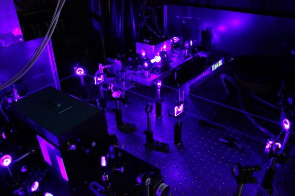
Detecting the small spin-flip frequency shift is challenging due to axial frequency noise, which, however, can be significantly reduced by cooling the ion. In the case of the proton/antiproton conventional cooling methods could suppress the noise sufficiently to allow for the detection of spin-flips [5,6]. For 3He2+, however, lower temperatures are required. To this end the so-called common endcap method will be implemented. Here, a single 3He2+ ion stored in one trap is sympathetically cooled by a cloud of laser-cooled beryllium ions in a neighboring trap. The interaction will take place by image currents induced into a common electrode shared by both traps [7].
In case of 3He+, nuclear spin-flip detection can be simplified via a novel detection scheme [7], where a state selective RF-pulse resonant with an electron transition probes whether a nuclear spin has occurred.

^ to the top

Setup

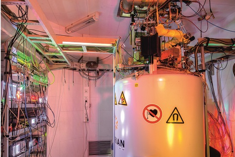
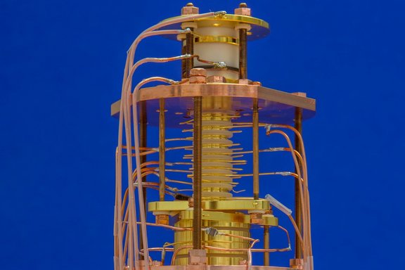
As shown in figure 4, the measurements of the g-factors are performed in a Penning-trap system consisting of cylindrical electrodes. The ions are produced internally using a field emission point and a 3He-filled quartz sphere which releases He atoms when heated. The Penning-trap tower is inserted into the cold bore of a 5 T superconducting magnet and cooled to 4 K by thermal contact with liquid helium. In order to excite electron spin-flips inside the apparatus, microwaves at a frequency of about 150 GHz need to be coupled into the trap tower via an oversized waveguide.

Penning-trap tower for the 3He+ hyperfine structure measurement.
Figure 4: Penning-trap tower for the 3He+ hyperfine structure measurement.


^ to the top

Status

The He ion source described above was tested in a Penning trap test setup and reliably produced 3He+ and 3He2+ ions. Figure 5 shows a resulting signal of a cloud of 3He2+ ions in the trap. The setup for the 3He+ hyperfine structure measurement has been finished.

Dip in the noise spectrum of the axial resonator measured with 3He2+ ions.
Figure 5: Dip in the noise spectrum of the axial resonator measured with 3He2+ ions.


^ to the top

References

[1]   A. Nikiel et al., Eur. Phys. J. D 68(11), 330 (2014) externer Link
[2]   G. W. Bennett et al., Phys. Rev. Lett. 92(16), 161802 (2014) externer Link
[3]   H. Iinuma, J. Phys.: Conf. Ser. 295(1), 012032 (2011) externer Link
[4]   A. Schneider et al., Ann. Phys. 531, 1800485 (2019) externer Link
[5]   G. Schneider et al., Science 358(6366), 1081 (2017) externer Link
[6]   C. Smorra et al., Nature 550, 371 (2017) externer Link
[7]   A. Mooser et al., J. Phys.: Conf. Ser.1138, 012004 (2018) externer Link