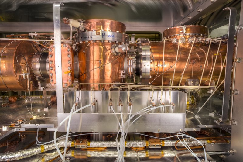
Der kryogene Speicherring CSR
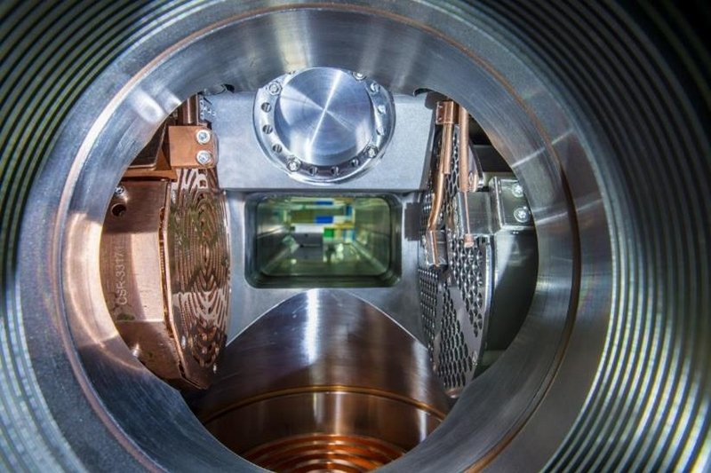
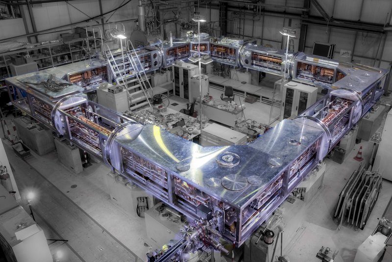
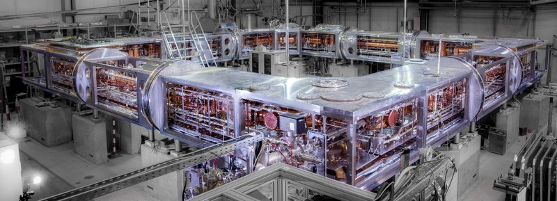
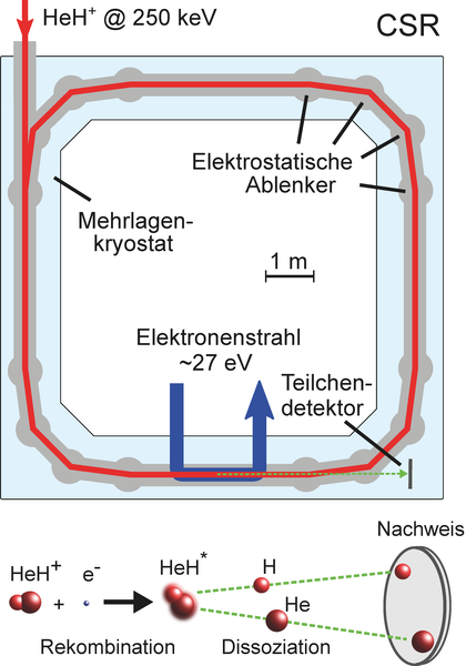
Der kryogene Speicherring (Cryogenic Storage Ring, CSR) am Max-Planck-Institut für Kernphysik ist der größte der neuen Generation von elektrostatischen Speicherringen weltweit. Mit einem Umfang von 35 m und einer vollständig elektrostatischen Ionenoptik eignet sich der CSR für die Durchführung detaillierter Kollisionsexperimente mit gespeicherten Atom- und Molekül-Ionen, nahezu unabhängig von deren Masse. Das innovative, mehrschichtige Kältetechnik-Konzept ermöglicht Experimente bei Kammer-Temperaturen von -268 ⁰C (oder 5 K) und bei einem extrem niedrigen Druck von etwa 10-16 Atmosphären. Atomare und molekulare Ionen können in einer nahezu störungsfreien Umgebung für viele Minuten bis hin zu mehreren Stunden (für schwerere Systeme) gespeichert werden. Der CSR ist mit einem Tieftemperatur-Elektronenkühler, einer einzigartigen Neutralstrahl-Apparatur und dem ersten vollständig kryogenen Reaktionsmikroskop ausgestattet, und ermöglicht damit vielseitige Experimente auf dem Bereich der molekularen Astrophysik und der Quantendynamik fundamentaler atomarer and molekularer Reaktionen.
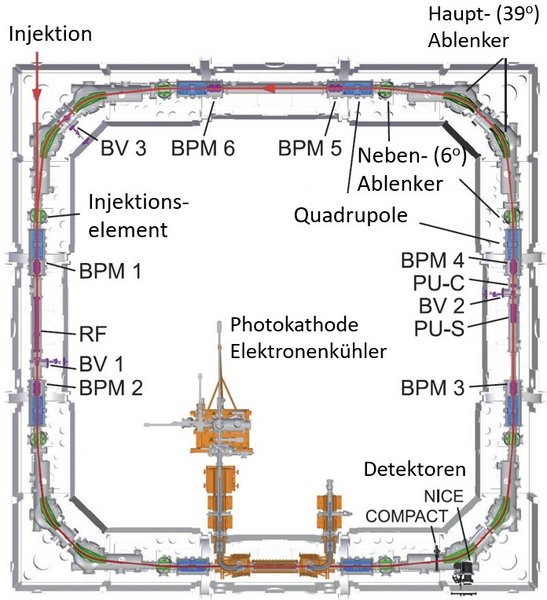
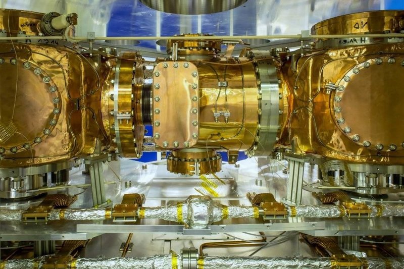
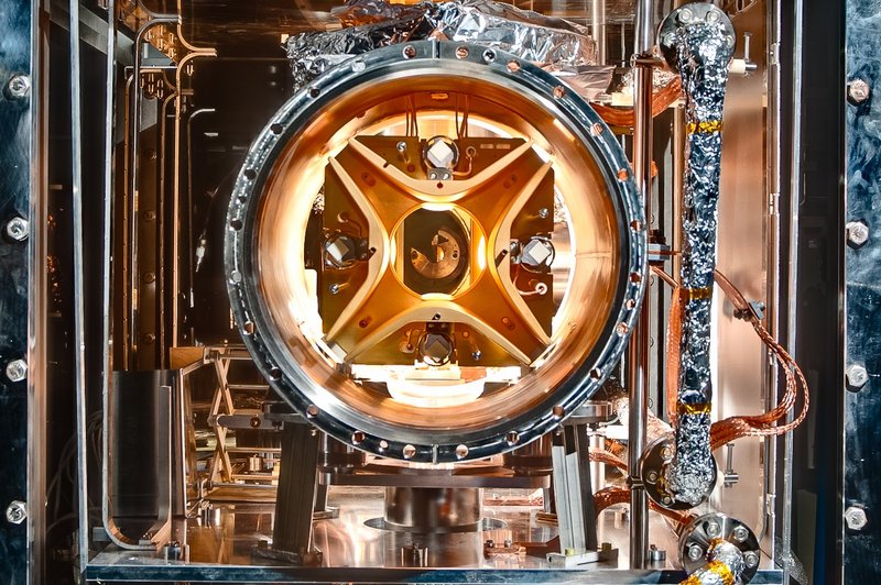
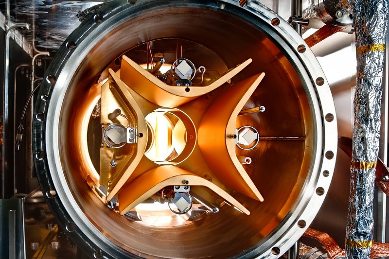
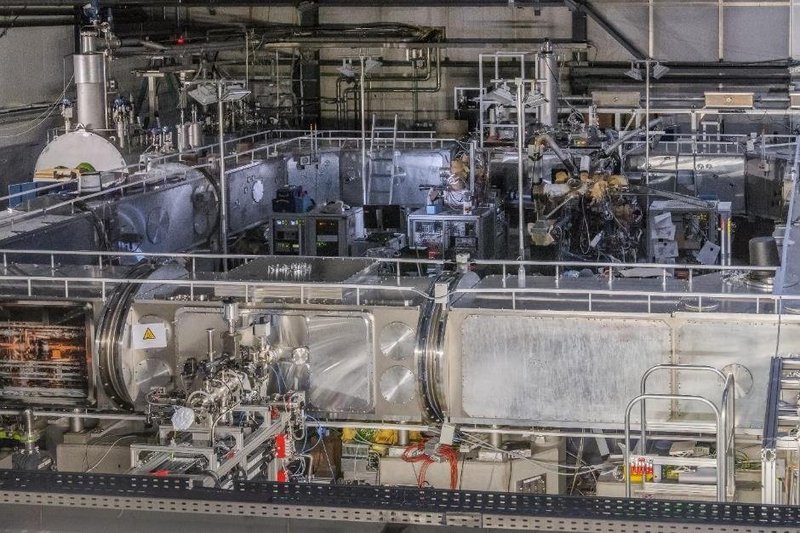
Das ionenoptische Layout des CSR vereint die Ansprüche der verschiedenen Experimentier-Stationen mit möglichst effektiver und vielseitiger Speichertechnik. Die gespeicherten Ionen werden bei kinetischen Energien von bis zu 300 keV pro Elementarladung durch elektrostatische Dipol- und Quadrupol-Deflektoren abgelenkt und fokussiert. In jeder der vier Ecken des CSR wird eine Ablenkung von 90 Grad vollzogen, aufgeteilt in je zwei 39-Grad und zwei 6-Grad Deflektoren. Dadurch wird eine möglichst große Akzeptanz für den gespeicherten Strahl erzielt, wobei gleichzeitig die Detektion von geladenen und neutralen Fragmenten an den verschiedenen Experimenten gewährleistet ist. Verschiedene Diagnoselemente für Strahlposition und Intensität sind über den Umfang des Speicherringes verteilt, und ermöglichen die nicht-destruktive Bestimmung der Strahlcharakteristika. Zwei elektrostatische Plattformen beschleunigen die Ionen auf Energien von bis zu 300 keV pro Ladungseinheit, bevor der Einschuss in den CSR erfolgt.
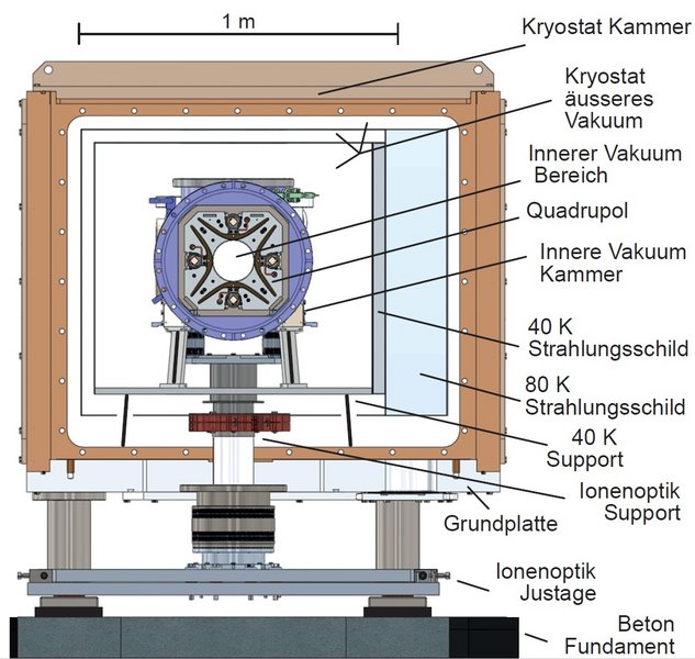
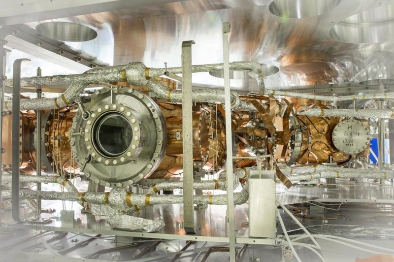
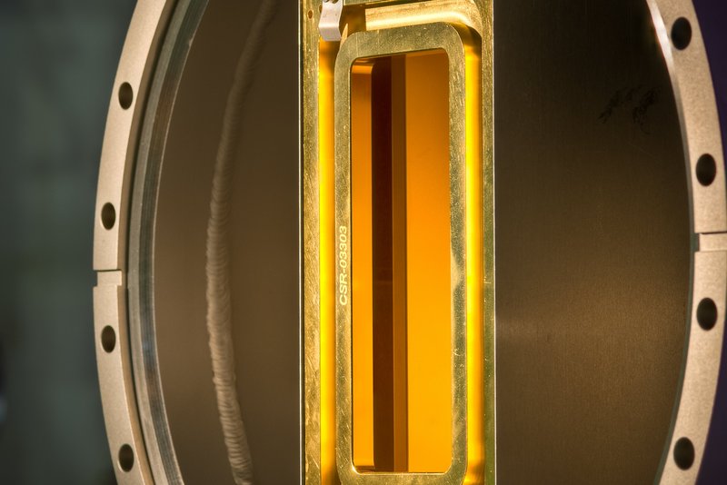
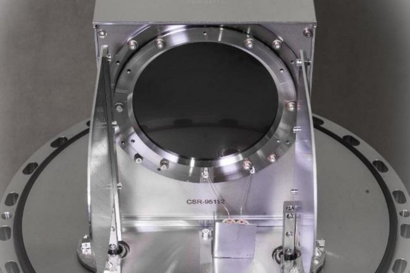
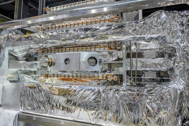
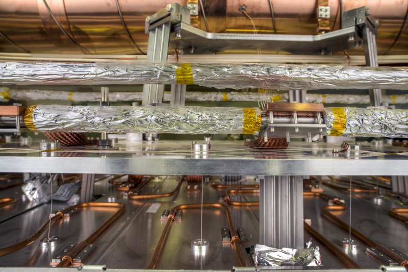
Das kältetechnische Konzept des CSR ist verknüpft mit der Maßgabe ein möglichst gutes Vakuum innerhalb der inneren Experimentierkammern zu erreichen. Dazu befinden sich in einer äußeren Kryostat-Struktur mehrere Lagen thermischer Isolation, die dazu dienen den Wärmefluss auf die Experimentierkammern bei einer Temperatur um 5 K (-268 ⁰C) auf ein Minimum zu reduzieren. Die Kryostat-Kammern werden von konventioneller Pumptechnik auf etwa 10-9 Atmosphären evakuiert. Die Kühlung der gesamten Anlage erfolgt durch einen geschlossenen Kreislauf verflüssigten Heliums, wobei das rückgeführte Helium verwendet wird um die mittleren Temperatur-Schilde bei 40 K bzw. 80 K zu halten. Durch die Kombination von evakuierten Kryostat-Kammern und Temperaturschilden kann sowohl die Konvektion als auch eine Strahlungserwärmung der inneren Kammern massiv unterdrückt werden.
Die extremen Bedingungen des Weltalls - mit niedrigen Temperaturen zwischen 10-100K, gepaart mit sehr geringen Teilchendichten – sind auf den ersten Blick unverträglich mit einem aktiven chemischen Netzwerk. Dennoch sind bereits etwa 300 verschiedene Molekül-Spezies im interstellaren Raum identifiziert worden. Moderne Observatorien wie der ALMA Teleskop-Verbund und das Weltraumteleskop JWST stellen immer detailreichere Bilder interstellarer Objekte bereit, um die molekulare Zusammensetzung unseres Universums zu enträtseln.
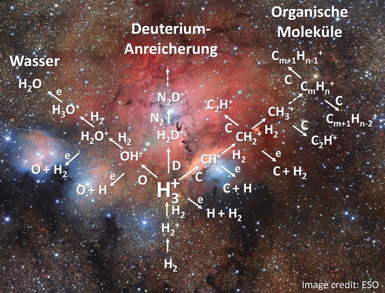
Der Schlüssel zur interstellaren Chemie in der Gasphase sind Prozesse, die von geladenen Molekül-Ionen initiiert werden. Diese Prozesse sind im Labor nur mit grossen Aufwand nachzustellen, weil die niedrigen Temperaturen ─ gepaart mit extremem Vakuum ─ nur schwer zu reproduzieren sind. Hinzu kommt die Schwierigkeit, dass die Erzeugung der geladenen Ionen in der Regel bei sehr hohen Temperaturen stattfindet, und Molekül-Ionen in undefinierten inneren Zuständen erzeugt, während die langen Zeitskalen im interstellaren Raum dafür sorgen, dass die meisten Moleküle in ihren niedrigsten Anregungszuständen vorliegen.
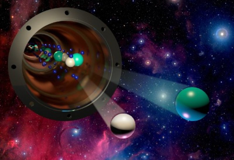
Hier bietet der CSR einzigartige experimentelle Bedingungen, die es erlauben Molekülbildung — und die ebenso wichtigen Dissoziationsprozesse — unter echten Weltraumbedingungen nachzustellen. Am Neutralstrahl-Experiment des CSR werden dazu intensive Strahlen von Atomen im Grundzustand erzeugt, um sie mit den gespeicherten Molekülen zu überlagern, und fundamentale chemische Reaktionen mit kalten Molekül-Ionen zu untersuchen. Am CSR Elektronenkühler kann der wichtige Dissoziative Elektroneneinfang untersucht werden, der maßgeblich die Häufigkeit vieler Molekül-Verbindungen in interstellaren Umgebungen beeinflusst.
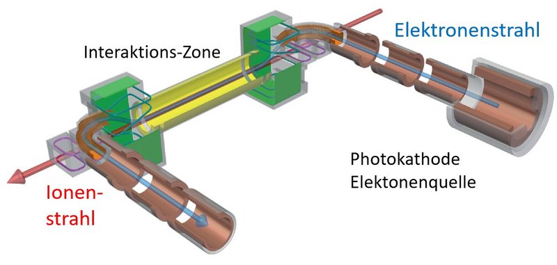
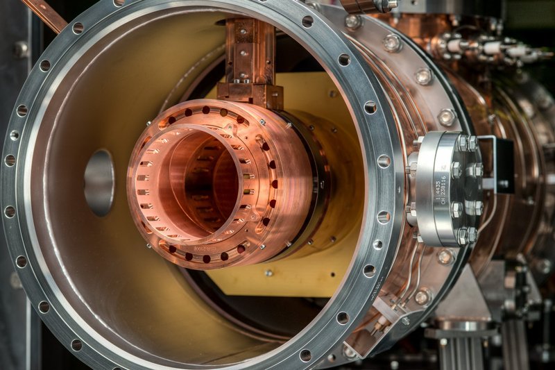
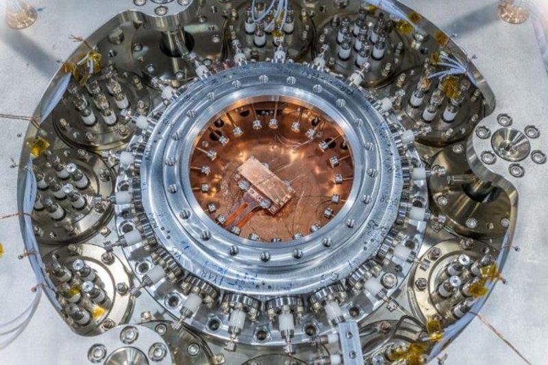
Die Kühlung von gespeicherten Ionen durch einen geführten Elektronenstrahl gleicher Geschwindigkeit ist eine etablierte Methode an magnetischen Speicherringen und bei Experimenten mit sehr hoher Strahlenergie. Am CSR stellt dieses Konzept jedoch eine enorme Herausforderung dar. Durch die vergleichsweise niedrige Strahlenergie und die große Masse von einfach geladenen Molekül Ionen muss ein Elektronenstrahl bei sehr niedriger Energie erzeugt werden. Der CSR Elektronenkühler ist die weltweit einzige solche Anlage an einem elektrostatischen Speicherring. Durch die Nutzung des Photoeffekts werden Elektronen-Ensembles mit niedriger Energieunschärfe aus einer Photokathode im Feld eines supraleitenden Magneten mittels eines fokussierten Lasers extrahiert.
Diese Elektronen werden von magnetischen Feldern geführt, adiabatisch expandiert und in den Speicherring eingekoppelt. Dort können sie mittels einer spannungsvariablen Driftstrecke auf Laborenergien von 1 eV abgebremst werden. Dadurch können sogar schwere Molekül Ionen, mit einem Gewicht von bis zu 160 atomaren Einheiten gekühlt und untersucht werden.
Neben der Translations-Kühlung durch die Coulomb-Interaktion, dient der kalte Elektronenstrahl auch als Kollisionspartner für die gespeicherten Ionen. Somit kann der Elektroneneinfang von atomaren und molekularen Ionen mittels spezieller kryogener Einzelteilchen-Detektoren für umgeladene oder neutralisierte Reaktionsprodukte innerhalb des CSR untersucht werden. Diese Prozesse sind von elementarer Bedeutung, z.B. für die molekulare Astrophysik und für atmosphärische Chemie.
Am CSR kommen sowohl kontinuierliche (Dauerstrich) als auch gepulste Lasersysteme zum Einsatz, welche an diversen Laserstrecken und Vakuum Ports in den CSR eingekoppelt werden können. Die Laserstrecken dienen einerseits zur spektroskopischen Diagnose und Manipulation interner Molekülanregungen, und andererseits zum Studium langsamer Kühlprozesse für eine ganze Bandbreite von Molekülen, von einfachen zwei-atomigen Verbindungen, bis hin zu komplexen Molekülen und Clustern.
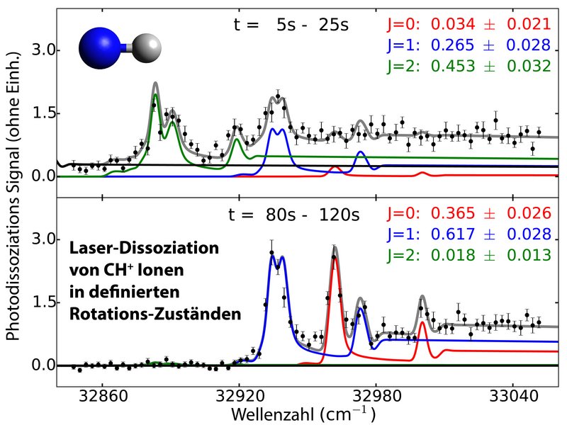
Dabei ist es am CSR gelungen das Kühlverhalten di-atomarer Molekül Ionen auf dem Level einzelner Quantenzustände zu verfolgen, und nachzuweisen, dass Infrarot-aktive Molekül Ionen innerhalb weniger Minuten auf die tiefsten Rotationszustände abkühlen. Die Moleküle befinden sich dann ─ ausreichend lange Speicherzeiten von Minuten bis Stunden vorausgesetzt ─ in den gleichen tiefen Anregungszuständen welche auch in kalten teil-ionisierten Plasmen wie dem interstellaren Raum besetzt sind.
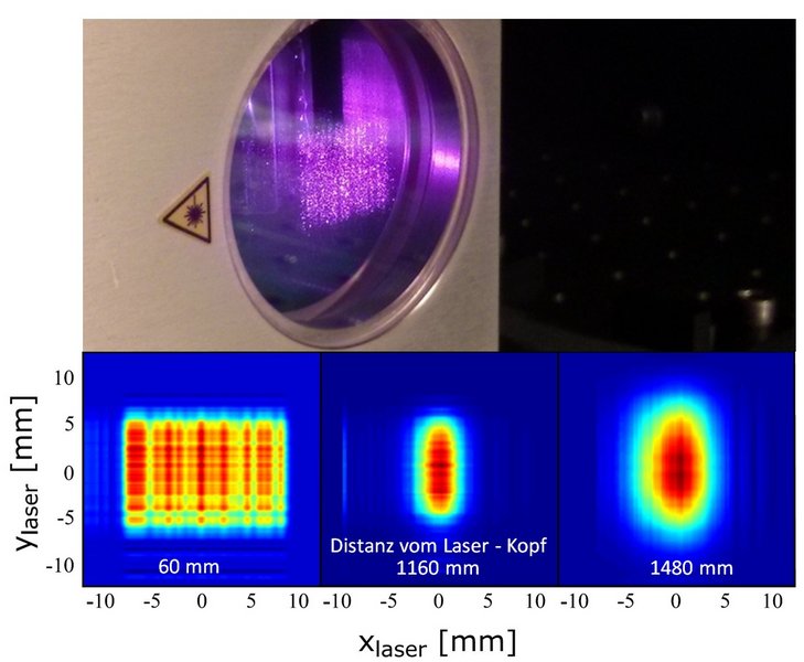
Neben den spektroskopischen Experimenten und der Diagnose angeregter Zustände werden Laser am CSR auch zur Neutralisation negativer Ionenstrahlen eingesetzt. Diese Technik kommt einerseits zum Einsatz um metastabile Zustände negativer atomarer Ionen, oder das Kühlverhalten negativ geladener Cluster zu studieren. Weiterhin wird die Laser-Neutralisation mit einem starken kontinuierlichen Laser-Array genutzt um starke, schnelle Atomstrahlen zu erzeugen. Diese Technik wird bisher am CSR als einzigem Speicherring eingesetzt, um Atomstrahlen gleicher Geschwindigkeit für Ionen-Neutral-Reaktionen im Speicherring bereitzustellen.
Die neueste Addition der experimentellen Stationen am CSR ist das weltweit erste kryogene Reaktionsmikroskop. Dieses Experiment ermöglicht die kinematisch komplette Analyse von atomaren und molekularen Stößen. Mehr dazu auf der Webseite der Abteilung Pfeifer.
Wir betreuen regelmäßig Bachelor- Master- und Doktorarbeiten in unserer Gruppe. Bei Interesse bitte einen der Gruppenleiter per E-Mail kontaktieren.
Dr. Florian Grussie
(CSR Technologie und experimentelle Anlagen)
PD Dr. Holger Kreckel
(Molekulare Astrophysik, Ionen-Neutral Reaktionen, Laser-Experimente)
Dr. Oldrich Novotny
(Molekulare Astrophysik, Elektronen-Kühlung und Elektronen-Kollisionen)
► Offene Master- und Bachelorarbeiten
31Characterization of a simple gas expansion ion source for intense pulses of subthermal molecular ions
L. Berger, F. Grussie, F. Nüßlein, O. Novotný, A. Znotins, J. Fréreux, X. Urbain, and H. Kreckel
Review of Scientific Instruments 96, 013301 (2025)
30Autodetachment of Diatomic Carbon Anions from Long-Lived High-Rotation Quartet States
V. C. Schmidt, R. Čurík, M. Ončák, K. Blaum, S. George, J. Göck, M. Grieser, F. Grussie, R. von Hahn, C. Krantz, H. Kreckel, O. Novotný, K. Spruck, and A. Wolf
Physical Review Letters 133, 183001 (2024)
29Unimolecular processes in diatomic carbon anions at high rotational excitation
V. C. Schmidt, R. Curík, M. Oncák, K. Blaum, S. George, J. Göck, M. Grieser, F. Grussie, R. von Hahn, C. Krantz, H. Kreckel, O. Novotný, K. Spruck, and A. Wolf
Physical Review A 110, 042828 (2024)
28Multiple differential electron spectra from detachment in collisions of 30–300-keV anions with atoms and molecules
M. Schulz, F. Herrmann, W. Zhang, D. V. Chicharro, A. Dorn, M. Grieser, F. Grussie, H. Kreckel, O. Novotny, F. Trost, A. Wolf, T. Pfeifer, C. D. Schröter, and R. Moshammer
Physical Review A 110, 022818 (2024)
27Dissociative recombination of rotationally cold ArH+
Ábel Kálosi, M. Grieser, L. W. Isberner, H. Kreckel, Åsa Larson, D. A. Neufeld, A. E. Orel, D. Paul, D. W. Savin, S. Schippers, V. C. Schmidt, A. Wolf, M. G. Wolfire, and O. Novotný
Physical Review A 110, 022816 (2024)
26Absolute rate coefficient measurements of the reactions of vibrationally cold HD+ and H3+ ions with neutral C atoms
F. Grussie, L. Berger, M. Grieser, Ábel Kálosi, D. Müll, O. Novotný, A. Znotins, F. Dayou, X. Urbain, and H. Kreckel
Physical Review A 109, 062804 (2024)
25Merged-Beams Study of the Reaction of Cold HD+ with C Atoms Reveals a Pronounced Intramolecular Kinetic Isotope Effect
F. Grussie, L. Berger, M. Grieser, Ábel Kálosi, D. Müll, O. Novotný, A. Znotins, F. Dayou, X. Urbain, and H. Kreckel
Physical Review Letters 132, 243001 (2024)
24Dissociative Recombination of Rotationally Cold OH+ and Its Implications for the Cosmic Ray Ionization Rate in Diffuse Clouds
Ábel Kálosi, L. Gamer, M. Grieser, R. von Hahn, L. W. Isberner, J. I. Jaeger, H. Kreckel, D. A. Neufeld, D. Paul, D. W. Savin, S. Schippers, V. C. Schmidt, A. Wolf, M. G. Wolfire, and O. Novotný
The Astrophysical Journal Letters 955, L26 (2023)
23Near-thermo-neutral electron recombination of titanium oxide ions
N. Jain, Ábel Kálosi, F. Nüsslein, D. Paul, P. Wilhelm, S. G. Ard, M. Grieser, R. von Hahn, M. C. Heaven, E. Miliordos, D. Maffucci, N. S. Shuman, A. A. Viggiano, A. Wolf, and O. Novotný
The Journal of Chemical Physics 158, 144305 (2023)
22Experimental Determination of the Dissociative Recombination Rate Coefficient for Rotationally Cold CH+ and Its Implications for Diffuse Cloud Chemistry
D. Paul, M. Grieser, F. Grussie, R. von Hahn, L. W. Isberner, Ábel Kálosi, C. Krantz, H. Kreckel, D. Müll, D. A. Neufeld, D. W. Savin, S. Schippers, P. Wilhelm, A. Wolf, M. G. Wolfire, and O. Novotný
The Astrophysical Journal 939, 122 (2022)
21Isochronous mass spectrometry in an electrostatic storage ring
M. Grieser, V. C. Schmidt, K. Blaum, F. Grussie, R. von Hahn, A. Kalosi, H. Kreckel, D. Müll, O. Novotný, F. Nüsslein, and A. Wolf
Review of Scientific Instruments 93, 063302 (2022)
20An ion-atom merged beams setup at the Cryogenic Storage Ring
F. Grussie, A. P. O’Connor, M. Grieser, D. Müll, A. Znotins, X. Urbain, and H. Kreckel
Review of Scientific Instruments 93, 053305 (2022)
19Laser-probing the rotational cooling of molecular ions by electron collisions
A. Kalosi, M. Grieser, R. von Hahn, U. Hechtfischer, C. Krantz, H. Kreckel, D. Müll, D. Paul, D. W. Savin, P. Wilhelm, A. Wolf, and O. Novotny
Physical Review Letters 128, 183402 (2022)
18Metastable states of Si− observed in a cryogenic storage ring
D. Müll, F. Grussie, K. Blaum, S. George, J. Goeck, M. Grieser, R. von Hahn, Z. Harman, Á. Kálosi, C. H. Keitel, C. Krantz, C. Lyu, O. Novotny, F. Nüsslein, D. Paul, V. C. Schmidt, S. Singh, S. Kumar, X. Urbain, A Wolf, and H. Kreckel
Physical Review A 104, 032811 (2021)
17An approach for multi-color action spectroscopy of highly excited states of H+3
A. Znotins, F. Grussie, A. Wolf, X. Urbain, and H. Kreckel
Journal of Molecular Spectroscopy 378, 111476 (2021)
16Quantum-state–selective electron recombination studies suggest enhanced abundance of primordial HeH+
O. Novotný, P. Wilhelm, D. Paul, A. Kalosi, S. Saurabh, A. Becker, K. Blaum, S. George, J. Göck, M. Grieser, F. Grussie, R. von Hahn, C. Krantz, H. Kreckel, C. Meyer, P. M. Mishra, D. Müll, F. Nüsslein, D. A. Orlov, M. M. Rimmler, V. C. Schmidt, A. Shornikov, A. S. Terekhov, S. Vogel, D. Zajfman, and A. Wolf
Science 365, 676-679 (2019)
15Roadmap on photonic, electronic and atomic collision physics: II. Electron and antimatter interactions
S. Schippers, E. Sokell, F. Aumayr, H. Sadeghpour, K. Ueda, I. Bray, K. Bartschat, A. Murray, J. Tennyson, A. Dorn, M. Yamazaki, M. Takahashi, N. Mason, O. Novotný, A. Wolf, L. Sanche, M. Centurion, Y. Yamazaki, G. Laricchia, C. M Surk, J. Sullivan, G. Gribakin, D. W. Savin, Y. Ralchenko, R. Hoekstra, and G. O'Sullivan
Journal of Physics B: Atomic, Molecular and Optical Physics 52, 171002 (2019)
14Astrochemical studies at the Cryogenic Storage Ring
H. Kreckel, O. Novotný, and A. Wolf
Philosophical Transactions of the Royal Society A: Mathematical, Physical and Engineering Sciences 377, 0412 (2019)
13Transfer matrix calculation for ion optical elements using real fields
P. M. Mishra, K. Blaum, S. George, M. Grieser, and A. Wolf
Nuclear Instruments and Methods in Physics Research Section A: Accelerators, Spectrometers, Detectors and Associated Equipment 885, 124-133 (2017)
12The phase slip factor of the electrostatic cryogenic storage ring CSR
M. Grieser, R. von Hahn, S. Vogel, and A. Wolf
Journal of Physics: Conference Series 874, 012049 (2017)
11Radiative Rotational Lifetimes and State-Resolved Relative Detachment Cross Sections from Photodetachment Thermometry of Molecular Anions in a Cryogenic Storage Ring.
C. Meyer, A. Becker, K. Blaum, C. Breitenfeldt, S. George, J. Göck, M. Grieser, F. Grussie, E. A. Guerin, R. von Hahn, P. Herwig, C. Krantz, H. Kreckel, J. Lion, S. Lohmann, P. M. Mishra, O. Novotny, A. O'Connor, R. Repnow, S. Saurabh, D. Schwalm, L. Schweikhard, K. Spruck, S. Kumar, S. Vogel, and A. Wolf
Physical Review Letters 119, 023202 (2017)
10Single-particle detection of products from atomic and molecular reactions in a cryogenic ion storage ring
C. Krantz, O. Novotny, A. Becker, S. George, M. Grieser, R. von Hahn, C. Meyer, S. Schippers, K. Spruck, S. Vogel, and A. Wolf
Nuclear Instruments and Methods in Physics Research Section A: Accelerators, Spectrometers, Detectors and Associated Equipment 851, 92-102 (2017)
9The Cryogenic Storage Ring CSR
R. von Hahn, A. Becker, F. A. Berg, K. Blaum, C. Breitenfeldt, H. Fadil, F. Fellenberger, M. Froese, S. George, J. Göck, M. Grieser, F. Grussie, E. A. Guerin, O. Heber, P. Herwig, J. Karthein, C. Krantz, H. Kreckel, M. Lange, F. Laux, S. Lohmann, S. Menk, C. Meyer, P. M. Mishra, O. Novotny, A. O'Connor, D. A. Orlov, M. L. Rappaport, R. Repnow, S. Saurabh, S. Schippers, C. D. Schröter, D. Schwalm, E. S. Schweikhard, T. Sieber, A. Shornikov, K. Spruck, S. Kumar, J. H. Ullrich, X. Urbain, S. Vogel, P. Wilhelm, A. Wolf, and D. Zajfman
Review of Scientific Instruments 87, 063115 (2016)
8Photodissociation of an internally cold beam of CH+ ions in a cryogenic storage ring
A. O'Connor, A. Becker, K. Blaum, C. Breitenfeldt, S. George, J. Göck, M. Grieser, F. Grussie, E. A. Guerin, R. von Hahn, U. Hechtfischer, P. Herwig, J. Karthein, C. Krantz, H. Kreckel, S. Lohmann, C. Meyer, P. M. Mishra, C. Novotny, R. Repnow, S. Saurabh, D. Schwalm, K. Spruck, S. Kumar, S. Vogel, and A. Wolf
Physical Review Letters 116, 113002 (2016)
7MOCCA: A 4k-Pixel Molecule Camera for the Position- and Energy-Resolving Detection of Neutral Molecule Fragments at CSR
L. Gamer, D. Schulz, C. Enss, A. Fleischmann, L. Gastaldo, S. Kempf, C. Krantz, O. Novotny, D. Schwalm, and A. Wolf
Journal of Low Temperature Physics 184, 839-844 (2016)
6Generation of neutral atomic beams utilizing photodetachment by high power diode laser stacks
A. O'Connor, F. Grussie, H. Bruhns, N. de Ruette, T.P. Koenning, K A. Miller, D.W. Savin, J. Stützel, X. Urbain, and H. Kreckel
Review of Scientific Instruments 86, 113306 (2015)
5Cryogenic micro-calorimeters for mass spectrometric identification of neutral molecules and molecular fragments
O. Novotny, S. Allgeier, C. Enss, A. Fleischmann, L. Gamer, D. Hengstler, S. Kempf, C. Krantz, A. Pabinger, C. Pies, D. W. Savin, D. Schwalm, and A. Wolf
Journal of Applied Physics 118, 104503 (2015)
4An efficient, movable single-particle detector for use in cryogenic ultra-high vacuum environments
K. Spruck, A. Becker, F. Fellenberger, M. Grieser, R. von Hahn, O. Novotny, S. Schippers, S. Vogel, A. Wolf, and C. Krantz
Review of Scientific Instruments 86, 023303 (2015)
3Maximum intensity, transmission limited cold electron beams from GaAs photocathode in the eV and sub-eV kinetic energy range
A. Shornikov, D. A. Orlov, C. Krantz, A.S. Jaroshevich, and A. Wolf
Physical Review Special Topics-Accelerators and Beams 17, 042802 (2014)
2The electrostatic Cryogenic Storage Ring CSR – Mechanical concept and realization
R. von Hahn, F. A. Berg, K. Blaum, J. Crespo López-Urrutia, F. Fellenberger, M. Froese, M. Grieser, C. Krantz, K. Kühnel, M. Lange, S. Menk, F. Laux, D. A. Orlov, R. Repnow, C. D. Schröter, A. Shornikov, T. Sieber, J. H. Ullrich, A. Wolf, M. Rappaport, and D. Zajfman
Nuclear Instruments and Methods in Physics Research Section B: Beam Interactions with Materials and Atoms 269, 2871-2874 (2011)
1The Cryogenic Storage Ring and its application to molecular ion recombination physics
C. Krantz, F. A. Berg, K. Blaum, F. Fellenberger, M. W. Froese, M. Grieser, R. von Hahn, M. Lange, F. Laux, S. Menk, R. Repnow, A. Shornikov, and A. Wolf
Journal of Physics: Conference Series 300, 012010, 1-8 (2011)
So funktioniert der CSR – ein kurzer Film
CSR Galerie