The H.E.S.S. Telescopes
- The Cherenkov technique
- Arrangement of the telescopes
- Mount and dish
- Mirror
- Camera
- Central trigger system
- Data acquisition
- Telescope monitoring
- Atmospheric monitoring
- Parameters of the HESS I and HESS II telescopes
For an overview of the H.E.S.S. I telescopes, see, e.g., the ICRC 2001 proceedings. See also the chronology of the construction of H.E.S.S. I (1994-2004) and images from the construction of the H.E.S.S. I telescopes.
The Cherenkov technique
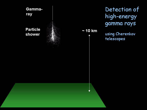
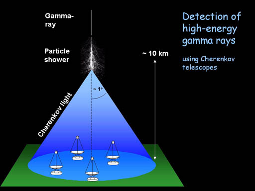
The detection of high energy gamma rays with the H.E.S.S. telescopes is based on the imaging air Cherenkov technique.
- An incident high-energy gamma ray interacts high up in the atmosphere and generates an air shower of secondary particles. The number of shower particles reaches a maximum at about 10 km height, and the shower dies out deeper in the atmosphere. Since the shower particles move at essentially the speed of light, they emit Cherenkov light, a faint blue light.
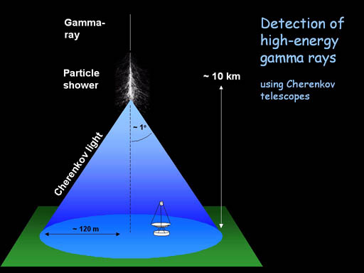
- The Cherenkov light is beamed around the direction of the incident primary particle and illuminates on the ground an area of about 250 m diameter, often referred to as the Cherenkov light pool. For a primary photon at TeV energy (1012 eV), only about 100 photons per m2 are seen on the ground. They arrive within a very short time interval, a few nanoseconds.
- A telescope located somewhere within the light pool will "see" the air shower, provided that its mirror area is large enough to collect enough photons. The "effective detection area" of a Cherenkov telescope is therefore given roughly by the area of the Cherenkov light pool, about 50000 m2, to be compared with the sub-m2 detection area of satellite instruments aiming to detect gamma rays before they interact with the atmosphere.
- The image obtained with the telescope shows the track of the air shower, which points back to the celestial object where there incident gamma ray originated. The intensity of the image is related to the energy of the gamma ray. The shape of the image can be used to reject unwanted "background", such as showers induced by cosmic ray particles.
- With a single telescope providing a single view of a shower, it is difficult to reconstruct the exact geometry of the air shower in space. The achieve this, multiple telescopes are used which view the shower from different points and allow a stereoscopic reconstruction of the shower geometry.
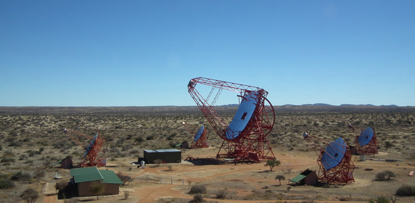
Arrangement of the telescopes
H.E.S.S. is a stereoscopic telescope system, where multiple telescopes view the same air shower.- The initial four H.E.S.S. telescopes (Phase I) are arranged in form of a square with 120 m side length, to provide multiple stereoscopic views of air showers. The telescope spacing represents a compromise between the large base length required for good stereoscopic viewing of the showers, and the requirement that two or more telescopes are hit by light generated by a shower. Showers emit their Cherenkov light at a height of about 10 km, and at a corresponding distance from the telescopes; hence even the 120 m spacing results in rather small angles between different views. On the other hand, given the 250 m diameter of the Cherenkov light pool, a larger spacing would make it increasingly unlikely that multiple telescopes are illuminated simultaneously.
- The diagonal of the square is oriented north-south.
- In Phase II of the project, an single huge dish with about 600 m2 mirror area was added at the center of the array, increasing the energy coverage, sensitivity and angular resolution of the instrument.
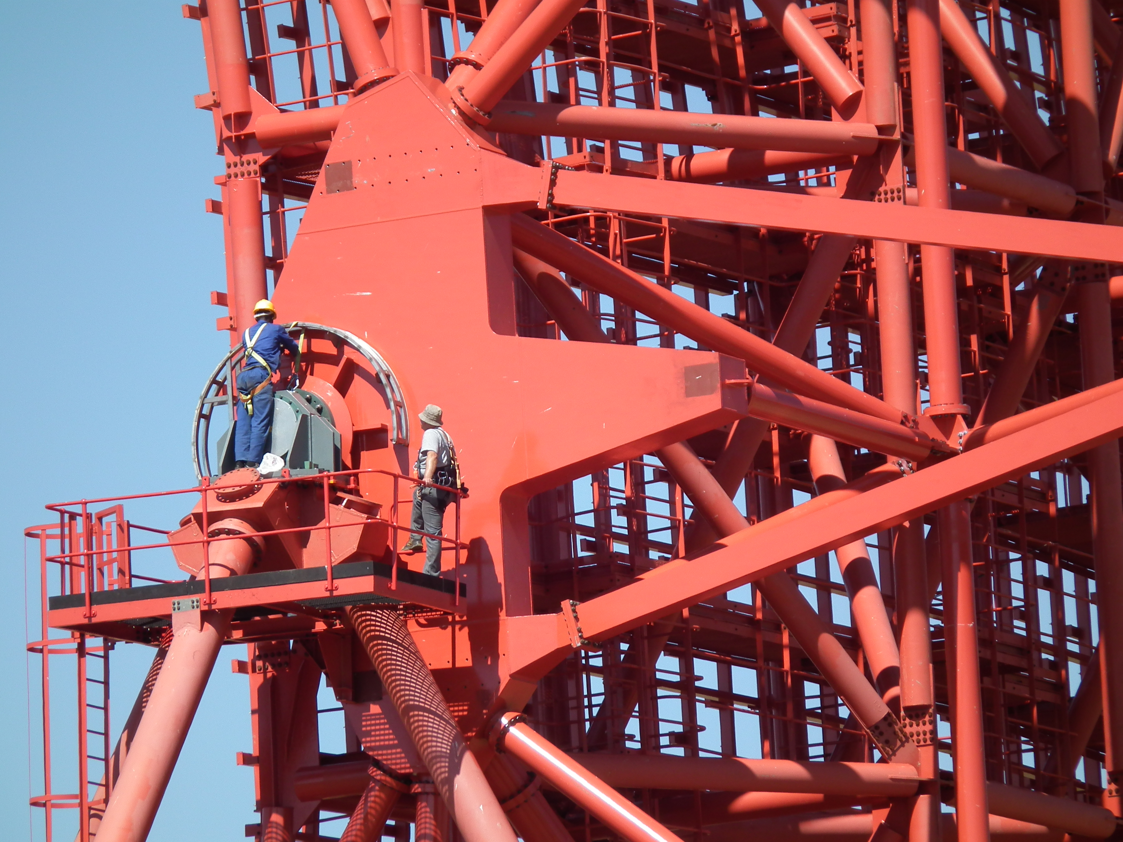
Mount and dish
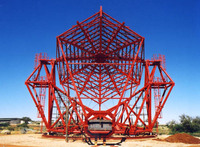
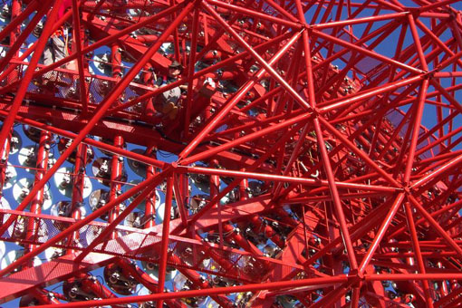
In the design of the H.E.S.S. telescopes, emphasis was placed on the mechanical stability and rigidity of the mount and dish.
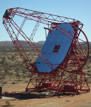
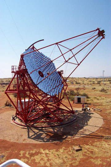
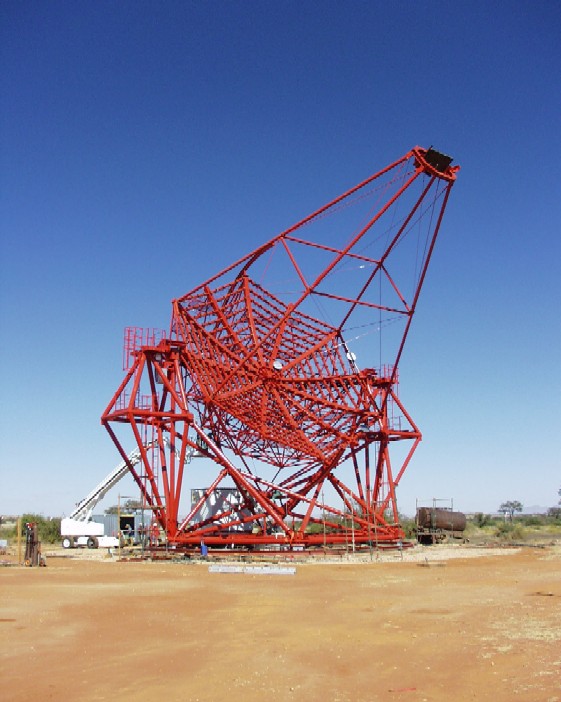
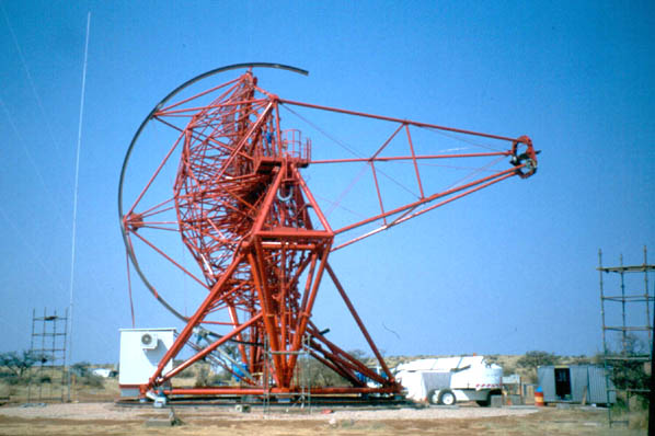
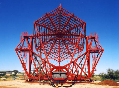
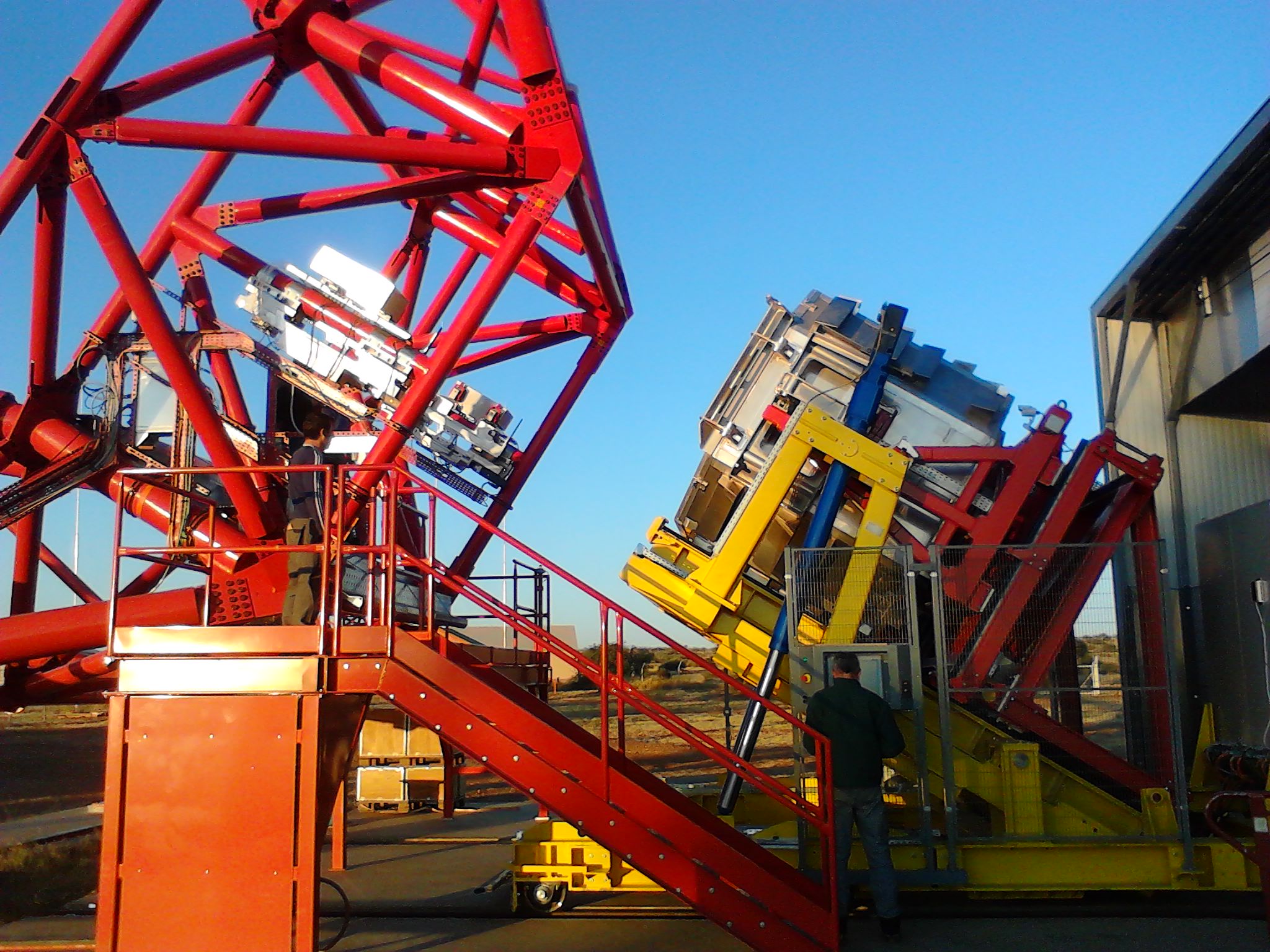
The 12 m H.E.S.S. I telescopes
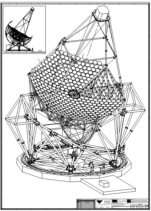
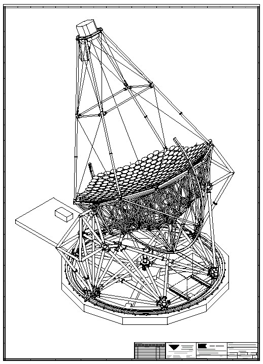
- The telescopes (here before mirror installation, side view, front view) use an alt-azimuth mount, to point the telescope at any point in the sky. A "base frame" rotates around a vertical axis and carries the dish, which rotates around the elevation axis. Both the base frame and the dish are realized as steel space frames. Technical drawings show a telescope from the front and back. Both axes are driven under computer control to track a celestial object across the sky.
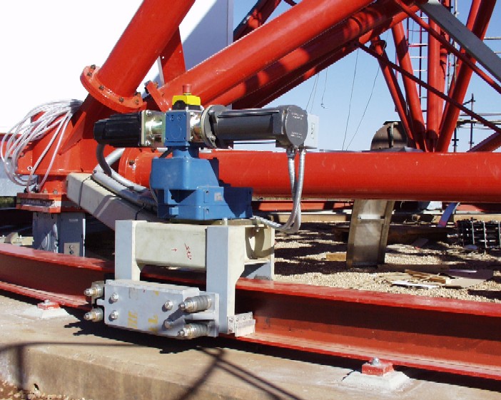
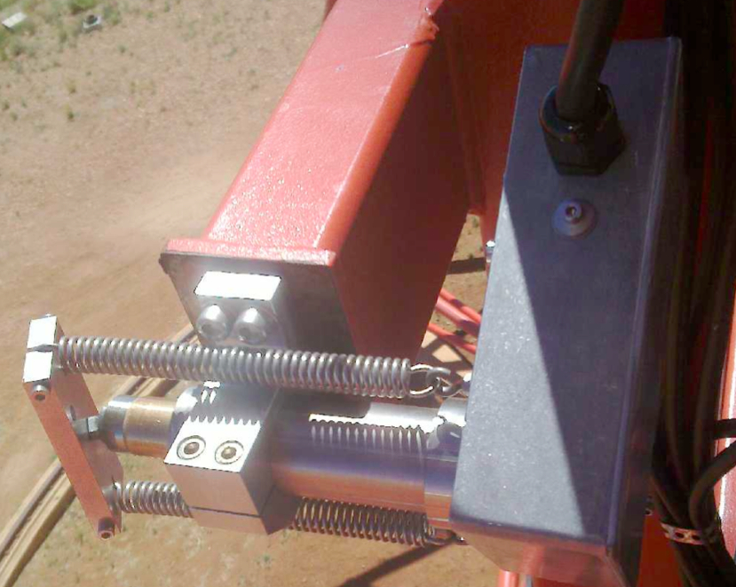
- The drive system combines for each axis a servo-controlled AC motor and a backup battery-driven DC motor. In order to reduce the drive forces, the drives act on circular rails of about 7 m radius. The maximum speed of the drive systems is about 100o/min, in order to allow rapid slewing from one object to another. The servo controllers and batteries for the DC drive are located in a small hut on the base frame.
- The pointing is controled by angular position encoders connected to both axes, which provide a resolution of a few arc-seconds (17 bit digitial readout plus an additional analog track). Telescope pointing is in addition monitored by an optical guide telescope (f=800 mm) equipped with a CCD camera, which serves to correct deviations from perfect pointing.
- Weights: complete telescope about 60 t incl. camera, drive systems, mirrors.
Detailed information about the telescope construction, the mirrors and their optical characteristics can be found in the publications:
- The optical system of the H.E.S.S. imaging atmospheric Cherenkov telescopes, Part I: layout and components of the system (1.8 MB)
- Part II: mirror alignment and point spread function (2.0 MB)
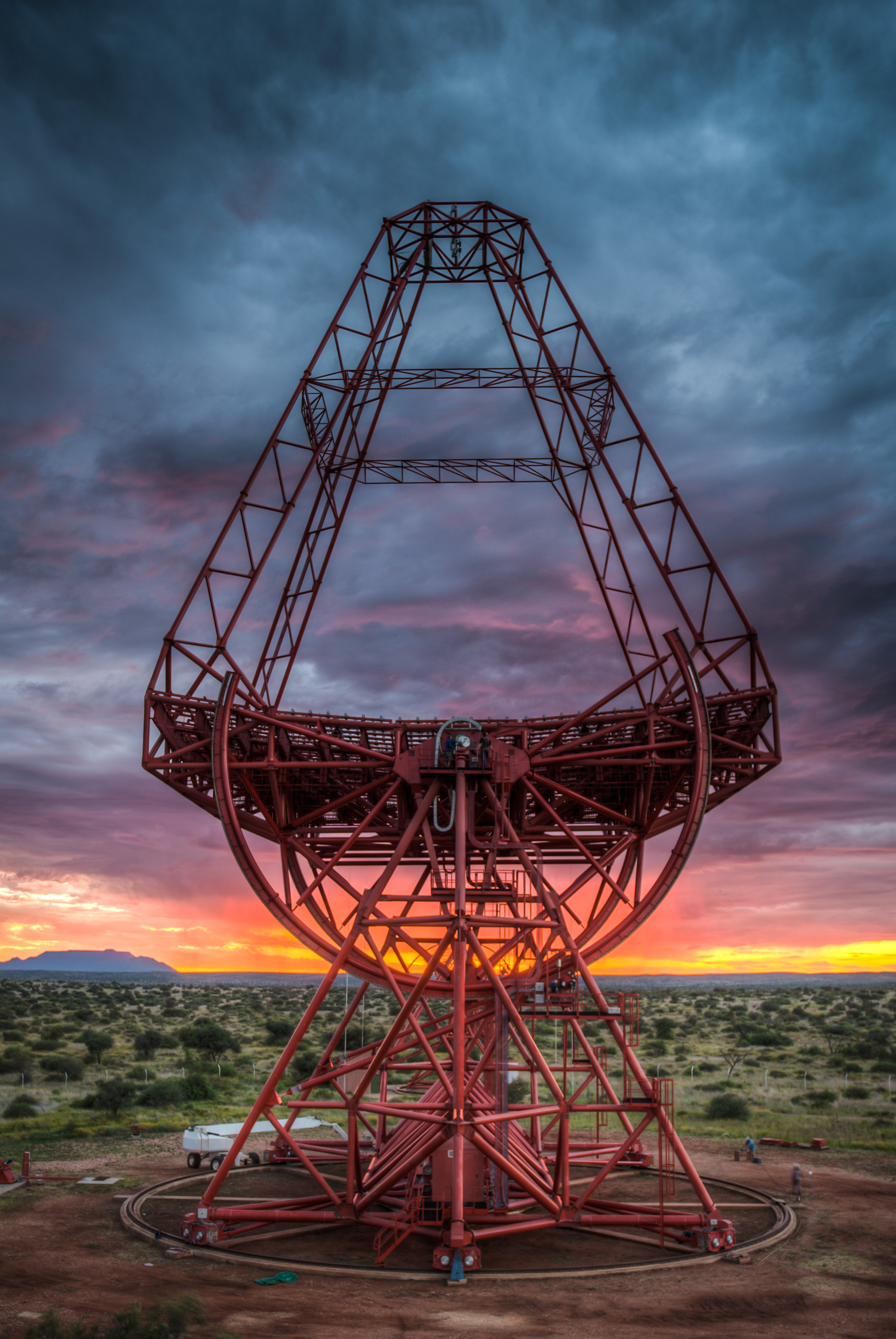
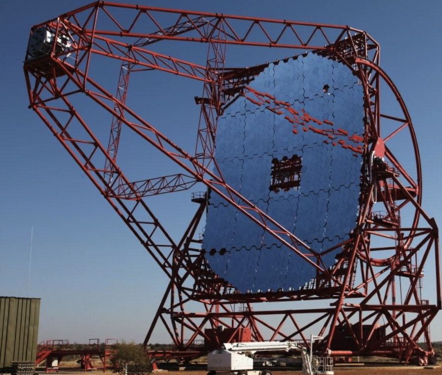
The 28 m H.E.S.S. II telescope
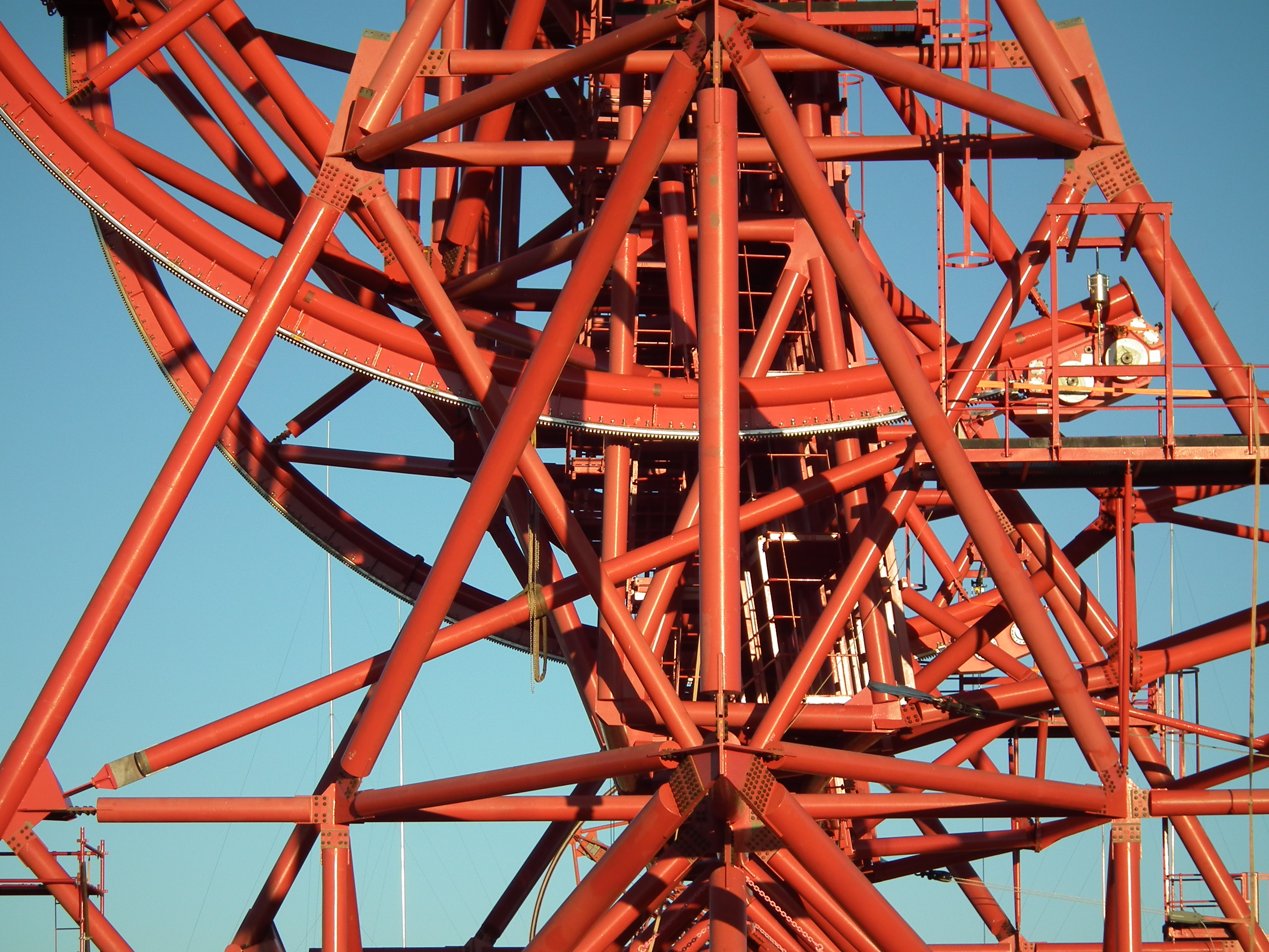
The design of the the H.E.S.S. II telescope structure follows the same guiding principles as for the 12 m telescopes: an alt-az mounted dish with high intrinsic rigidity. The basic parameters of the telescope are
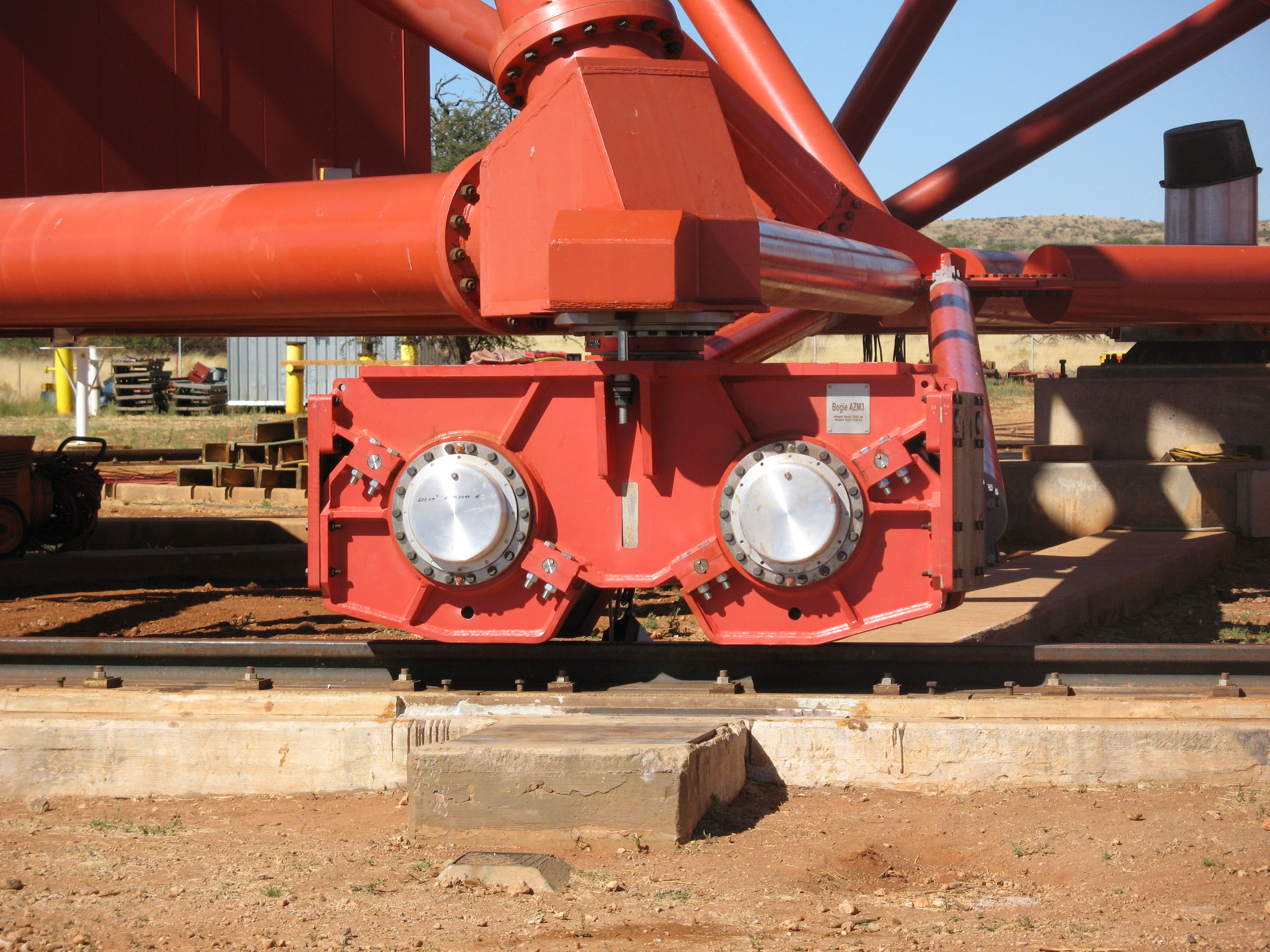
- Azimuth drive system: 12 wheels in 6 bogies on 36 m diameter rail; 4 wheels driven by motors; peak positioning speed 200 degr./minute; range +– 280 degr. from park position;
- Height of elevation axis: 24 m
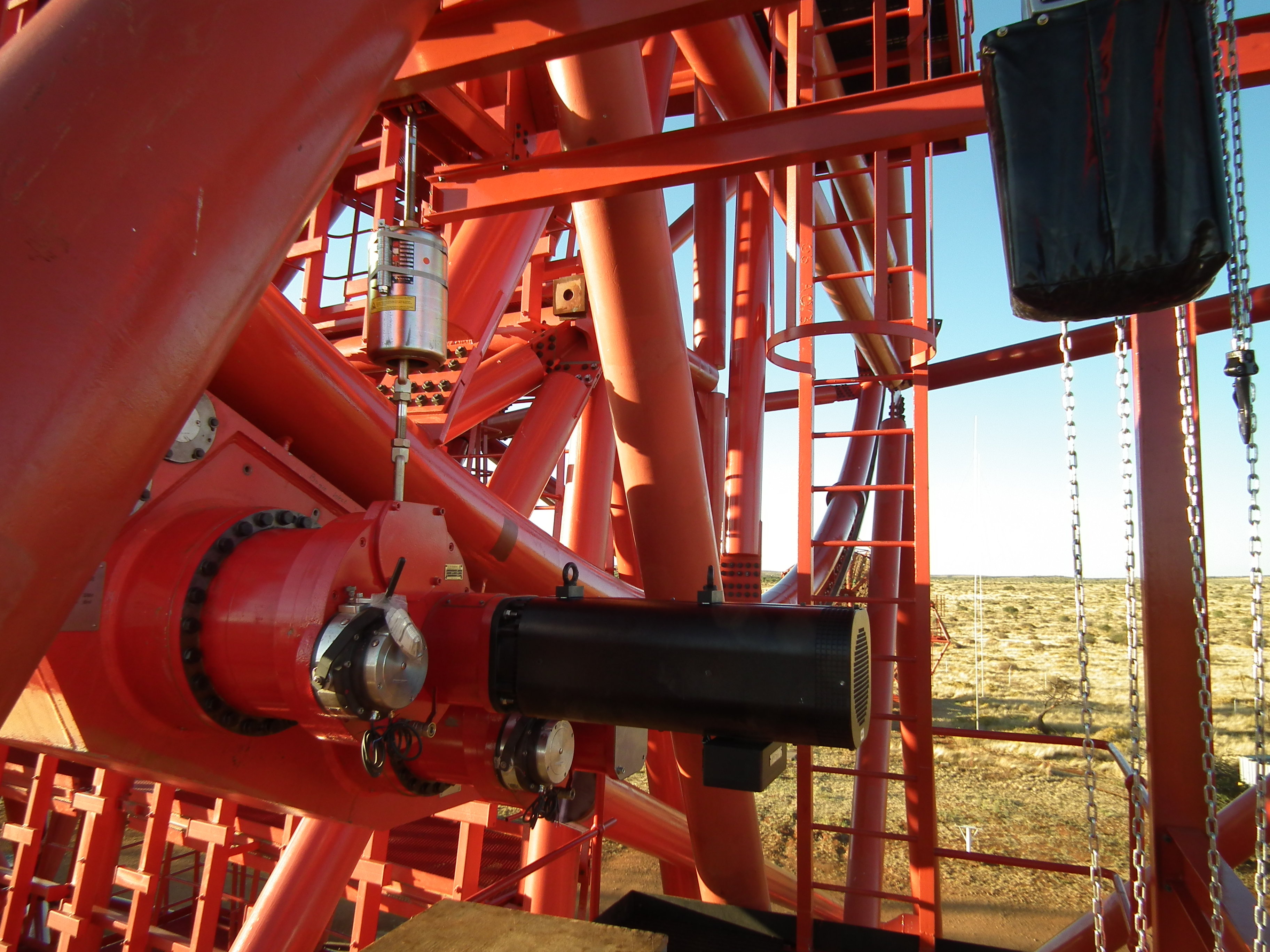
- Elevation drive system: Rack and pinion on either side of the dish; 2 drive units with 2 motors each; peak positioning speed 100 degr./minute; range –125 degr. +90 degr. from vertical;
- Dish dimensions 32.6 m by 24.3 m, equivalent to 28 m circular dish
The weight of the complete H.E.S.S. II telescope amounts to 580 tons.
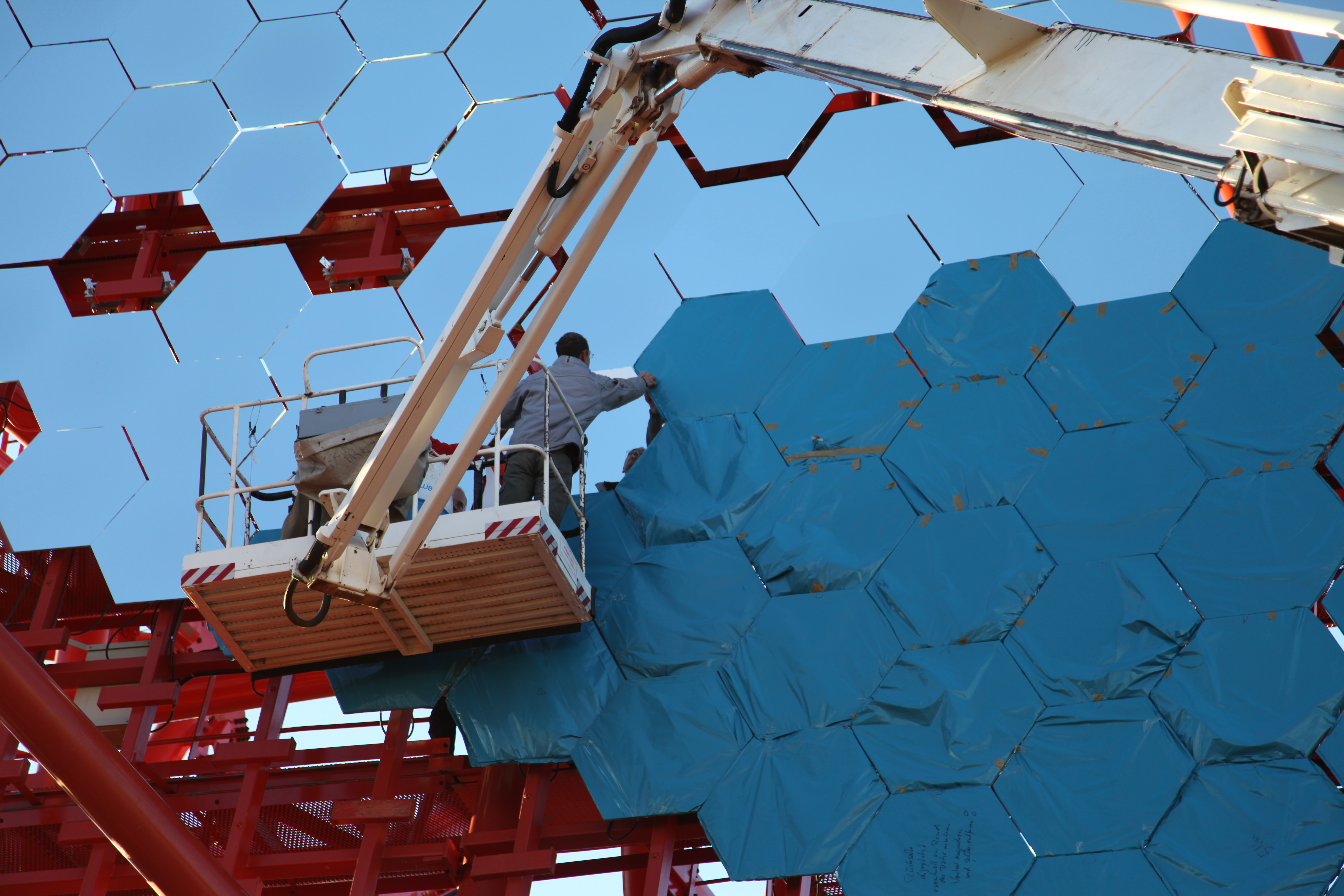
Mirror
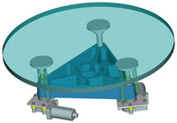
The mirror focuses the Cherenkov light of an air shower onto the camera. Relevant for the performance of a telescope are the net mirror area and the quality of the image, i.e. the point spread function (size of the image of a point source).
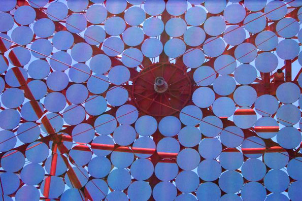
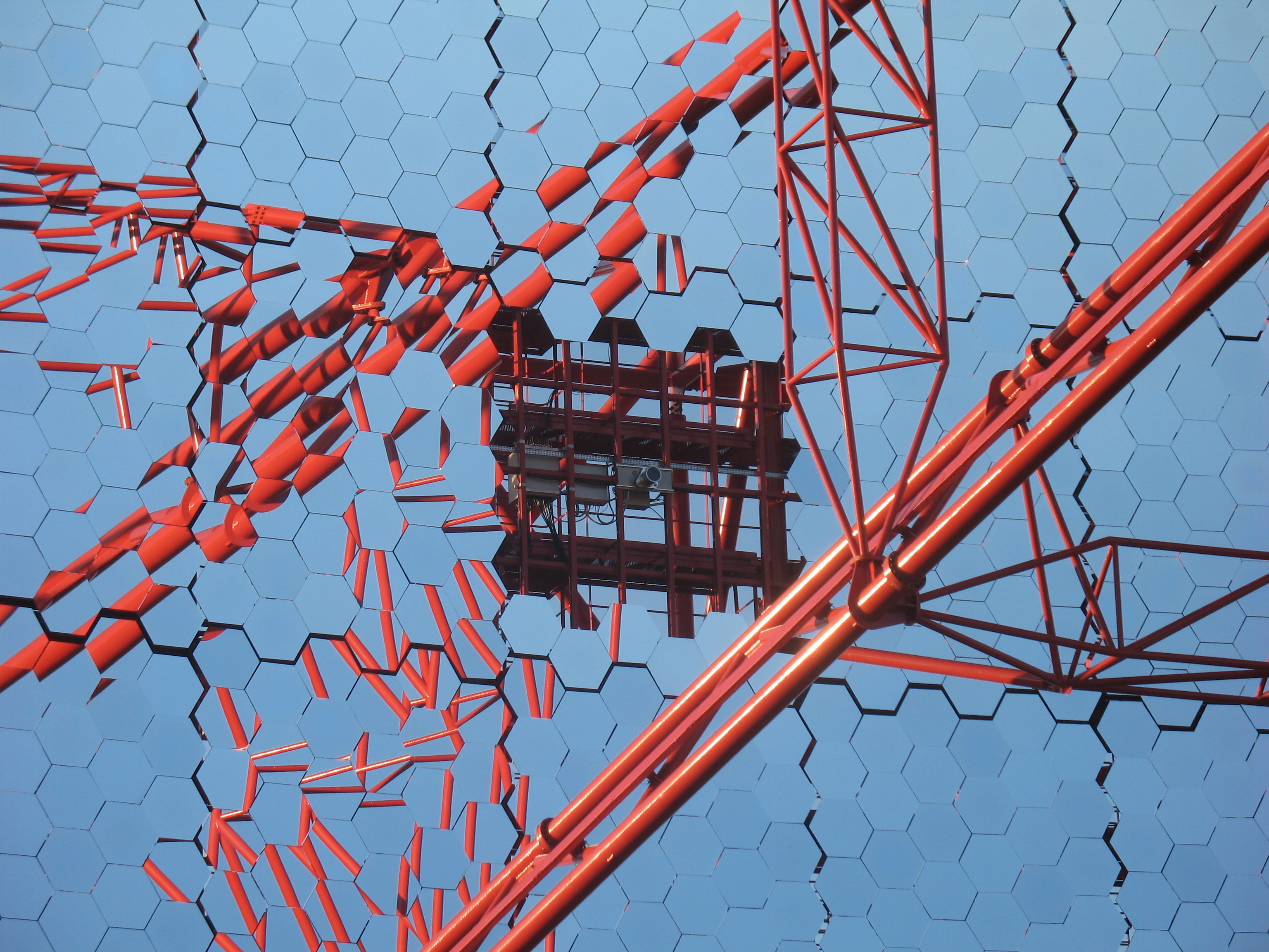
The 12 m H.E.S.S. I mirrors
- For cost reasons, the mirror is segmented into 382 round mirror facets of 60 cm diameter, made of aluminized glass with a quartz coating.
- The mirror has a focal length of 15 m and a d/f ratio of 0.8; the mirror facets are arranged in a Davies-Cotton design (on a sphere of radius f), which provides good imaging also for off-axs rays.
- The total mirror area is 108 m2 per telescope.
- Mirror reflectivity is >80% (300 to 600 nm). Each mirror tile is individually tested for reflectivity and image quality before it is mounted.
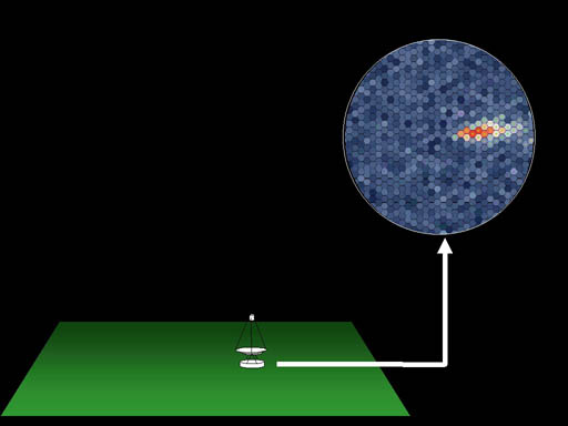
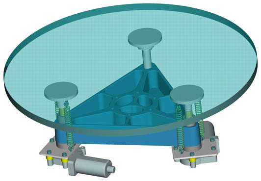
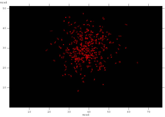
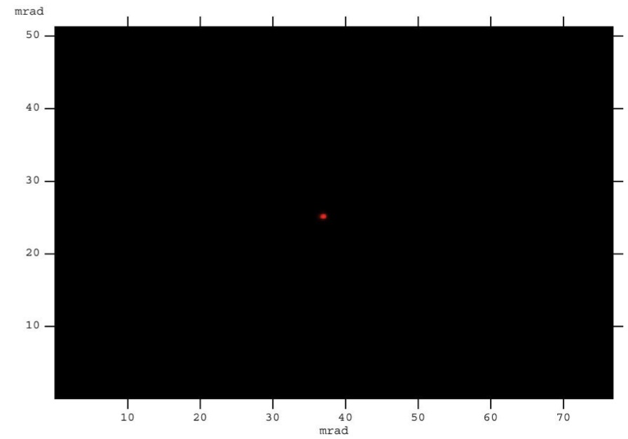
- The orientation of each facet is adjustable by two remote-controlled motors. To align the mirror facets, the image of a star in the focal plane is viewed by a CCD camera in the center of the dish. Before alignment of the facet, each facet generates a light spot. One mirror at a time, the individual mirrors are then moved until all spots converge in the center. The procedure is fully automatic; the initial alignment requires a few nights. The effect of the alignment is visualized by comparing the image of a star before and after alignment. Alignment of mirror will be check regularly; when required, a re-alignment can proceed in a few hours.
- The mirrors of H.E.S.S. telescopes are focused for an object distance of about 10 km, corresponding to the typical distance of an air shower from the telescopes.
- The specified point spread function including alignment errors is 0.03o (rms) on axis (0.5 mrad), 0.06o (1 mrad) for rays 2o off axis. The measured point spread functions exceed. Over most of the field of view, the spot is well contained within a single pixel (indicated in the figure by its hexagonal outline). Consistent with raytracing simulation, the spot width increases with increasing angle to the optical axis. Caused by gravity-induced deformations of the dish, the point spread function varies slightly with elevation; the degree of variation is as predicted by FEM simulations and is uncritical.
Detailed information the telescope mirror, its alignment and optical characteristics can be found in the publications The optical system of the H.E.S.S. imaging atmospheric Cherenkov telescopes, Part I: layout and components of the system (1.8 MB) and Part II: mirror alignment and point spread function (2.0 MB).
The 28 m H.E.S.S. II mirror
The H.E.S.S. II telescope uses a parabolic mirror shape to minimize time dispersion. The parabolic shape is approximated by a grid of 5 x 5 planar mirror support segments, aligned to approach a parabola. Hexagonal rather than round facets optimize coverage. Facets are also larger than for the H.E.S.S. I telescopes, with about 2.5 times larger area per facet. Mirror parameters are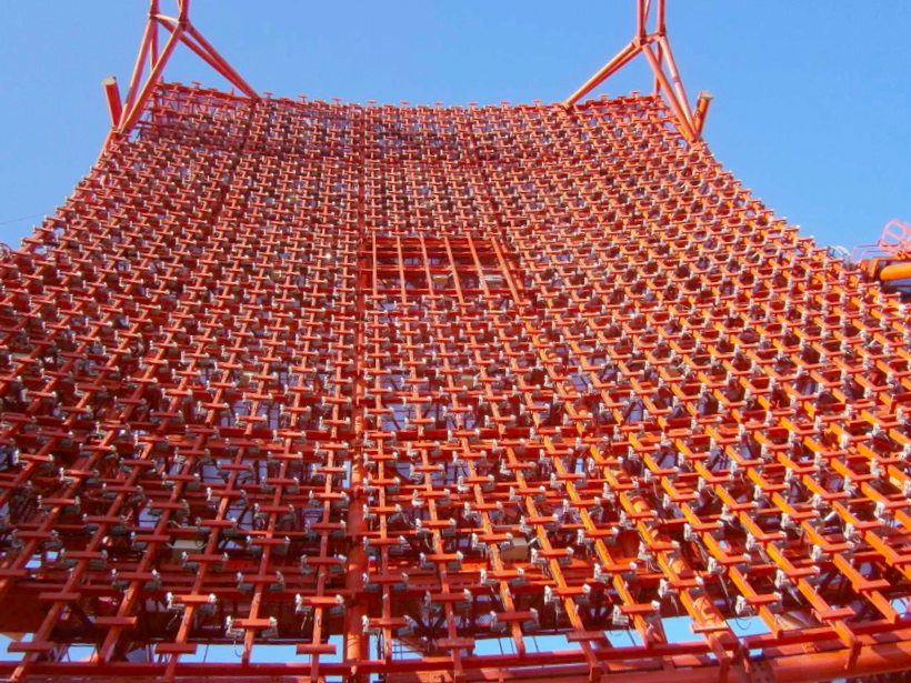
- Focal length: 36 m
- Total mirror area: 614 m2
- Mirror facets: 875 hexagonal facets of 90 cm (flat-to-flat) size; quartz-coated aluminized glass; weight per facet approx. 25 kg
- Facet alignment: each facet is equipped with 2 actuators with 2 μm positioning step size, corresponding to a 1 arc second facet tilt
Camera
The cameras of the H.E.S.S. telescopes serve to capture and record the Cherenkov images of air showers. Design criteria included a small pixel size to resolve image details, a large field of view to allow observations of extended sources and surveys, and a triggering scheme which allows to identify the brief and compact Cherenkov images and to reject backgrounds, such as the light of the night sky. The complete electronics for image digitization, readout and triggering is integrated into the camera body.
Cameras of the 12 m telescopes
- A 5o field of view.
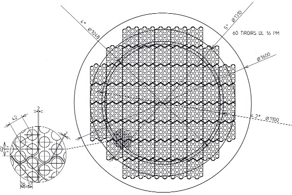
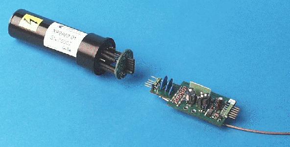
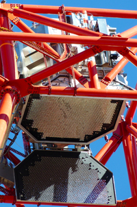
- 960 photon detector elements ("pixels", see front face of the camera), each subtending 0.16o angle, using 29 mm, 8-stage photomultiplier tubes (PMTs) with borosilicate windows, equipped with Winston cones to improve light collection, operated at a gain of 2x10⁵. Operating voltages for the PMTs are supplied by DC-DC converters integrated into each PMT base, with active stabilization for the last four dynodes for best linearity. A PMT with its base.
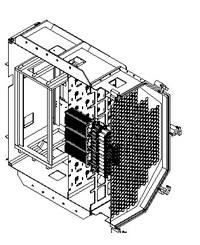
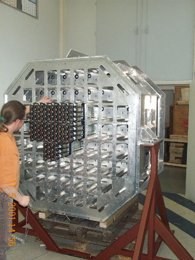
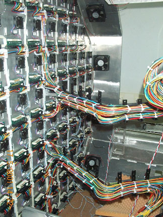
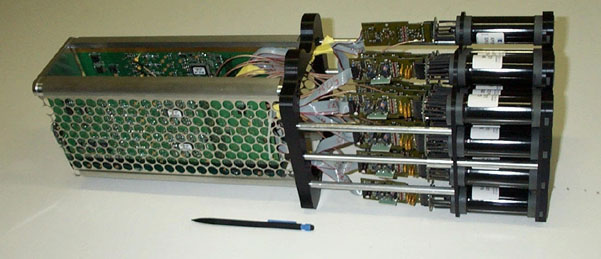
- Modular construction using 60 "drawers" which slide into the camera body (Exploded view of the camera body, cut-away few of the camera body, front view of the actual camera body, view into the rear section). Each drawer contains 16 PMTs and the associated electronics. The rear part of the camera houses power supplies and crates with interfaces to the digital readout bus, with a CPU and with the trigger processors.
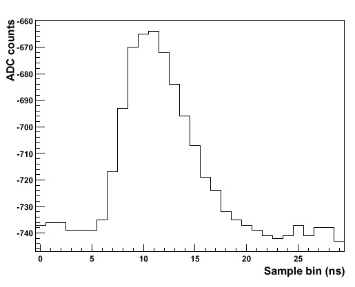
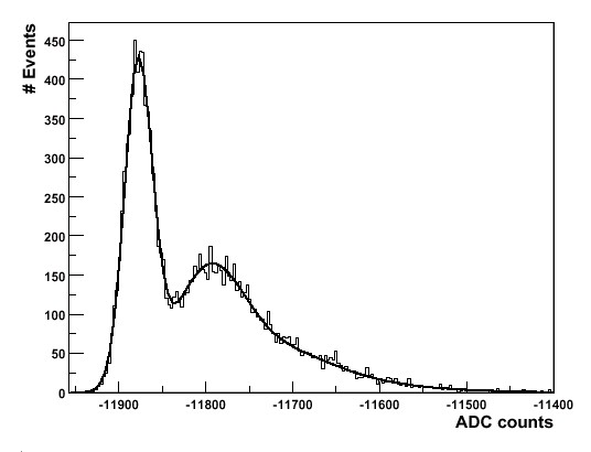
- PMT signals are captured using dual-range 1 GHz Analog Ring Sampling ASICs (NECTAr chip) which sample the signal every nanosecond and which record the last 1024 ns of signal history. The signal processing provides a dynamic range of 0.1 to more than 2000 photoelectrons. Here a trace of a signal sampled by the analogue memories, and the pulse-height distribution measured for single photoelectrons, illustrating the resolution and noise performance.
- The camera is triggered by a coincidence of signals detected in 3 to 5 pixels in (overlapping) 8x8 pixel sectors; typical signals required in a pixel ("pixel trigger thresholds") are around 5 photoelectrons. The fast coincidence circuitry provides an effective coincidence window of about 1.5 ns, and allows for the efficient rejection of uncorrelated PMT signals caused by photons of the night sky background light.
- Once a camera triggers on a shower image, it alerts a central trigger station. If two or more telescope trigger simultaneously, providing stereo images of an air shower, a trigger confirmation is sent back to the telescope, and the analog signals stored in the ARS are digitized, processed, and read out via a readout bus into the local processor of the camera.
- Monitoring circuitry inside each drawer provides information of PMT currents, PMT trigger rates, supply voltages and temperatures.
- Air cooling is used to remove close to 5 kW of heat dissipated in the circuitry of the camera. Air flow is provided by about 80 computer-controlled fans.
- Camera dimensions: about 1.6 m diameter, 1.5 m length; weight about 800 kg.
More details about the camera are given, e.g., in the ICRC 2017 proceedings. The processing and calibration of the camera data is described here.
The camera of the 28 m telescope
- Photo sensors: 2048 1-1/4’ photo multipliers
- Pixel size: 42 mm (hexagonal, flat-to-flat), equivalent to 0.067 degr.
- Sensitive area / field of view: 200 cm Ø, equivalent to 3.2 degr. on the sky
- Signal recording: 1 GHz signal sampling; 2 gain channels for each pixel for large dynamic range; records signal amplitude, timing, and shape
- Effective signal integration time: 16 nano-seconds
- Image recording rate: 3600 images/second
- Power consumption: 8 kW
- Dimensions of camera body: 227 cm wide x 240 cm high x 184 cm deep
- Camera weight: 2.8 tons
- Camera support: Quadrupod
Central trigger system
H.E.S.S. employs the stereoscopic reconstruction of air showers to determine their direction in space, the type and the energy of the primary particle. Therefore, only air showers which generate images in at least two telescopes are recorded. This requirement reduces the load on the DAQ system, reduces the read-out dead time and allows the trigger thresholds and energy thresholds to be lowered. The central trigger system receives trigger signals from the individual telescopes and searches for coincidences between telescopes, properly accounting for the delays of the signals from the different telescopes, and their dependence on telescope pointing. Coincident triggers result in the read-out of telescope data; for non-coincident triggers, the telescope readout electronics is cleared after a few microseconds and is ready for the next event.
The central trigger system is described in the publication The trigger system of the H.E.S.S. telescope array.
To include the 28 m H.E.S.S. II telescope, the central trigger system was upgraded, it now allows triggering on arbitrary combinations of the five telescopes. The usual operating mode is that either a concidence of any two of the five telescopes will trigger image readout, but that also air showers seen only in the 28 m telescope will be recorded, to provided minimal energy threshold.Data acquisition
The data acquisition system (DAQ) serves to collect data from the telescopes and monitoring instruments on site. Once collected, it is processed by the DAQ and a real time analysis is performed. Data is stored locally on RAID servers and tapes are used for distribution to Europe; however, a small fraction of monitoring data is transmitted using the Internet.
- The local network consists of several 1 Gb HP ProCurve 2510G series switches which are also used to send data to the different telescopes.
- The processor farm consists of 10 SuperMicro worker nodes each with two Intel Xeon E5450 3.0 GHz quad core CPUs and 16 GB DDR2 RAM. Five SuperMicro servers each equipped with a 12 TB RAID6 plus Hot Spare are used for storage.
- The worker nodes are used to combine the data from the different telescopes into complete events. These events are then analyzed in real time on the nodes and, together with all available monitoring information, stored to disk on the servers.
- The DAQ software is written in C++ and Python, it uses the omniORB implementation of the CORBA standard for interprocess communication and ROOT for data storage and as an analysis framework.
Telescope monitoring
Permanent monitoring of the performance of the telescopes is crucial to achieve optimum data quality. Currents and counting rates of the camera photon detectors are continuously recorded, as are the temperatures in all parts of the camera. Additional monitoring instruments include
- A laser light pulser in the center of the dish, which illuminates the camera uniformly and is used to flat-field the camera.
- A "sky CCD" with an f=800 mm telescope, mounted parallel to the optical axis on the telescope and employed to correct telescope pointing using stars.
- A "lid CCD" mounted in the center of the dish and viewing the camera, used to align mirrors and to monitor the point spread function by viewing the images of stars on the white camera lid, and to monitor deformations of the camera masts under gravity by viewing reference LEDs on the camera body.
Atmospheric monitoring
Atmospheric parameters and optical transmission of the atmosphere need to be known in order to relate the measured Cherenkov light yield and the energy of the incident particle. Instruments used in H.E.S.S. to probe the atmosphere will include
- Infrared radiometers on each telescope to measure the effective sky temperature in the field of view of the telescope. Clouds in the field of view manifest themselves through an increased sky temperature.
- A scanning infrared radiometer to survey the entire sky every few minutes.
- A "ceilometer", an active cloud sensor scanning the sky with a laser beam and detecting light backscattered by clouds and aerosols.
- An optical telescope measuring atmospheric transmission using stars.
- A weather station.
W. Hofmann, July 2012